Shower gel processing system, shower gel processing method and shower gel

A processing system, shower gel technology, applied in chemical instruments and methods, dissolving, bottle filling, etc.

Active Publication Date: 2019-05-17
浙江英树生物科技有限公司
View PDF6 Cites 16 Cited by
  • Summary
  • Abstract
  • Description
  • Claims
  • Application Information

AI Technical Summary

Problems solved by technology

The design of the automatic filling device for the bagged mineral salt shower gel is reasonable, and the automatic filling of the shower gel is realized through the conveyor belt body and the filling nozzle, and the automatic capping can be realized through the rotating motor and the bag cover fixing clip; the utility model The disadvantage is that the same amount of shower gel cannot be efficiently placed in each shower gel bottle

Method used


Image

  • Shower gel processing system, shower gel processing method and shower gel
  • Shower gel processing system, shower gel processing method and shower gel
  • Shower gel processing system, shower gel processing method and shower gel

Examples


specific Embodiment approach 1

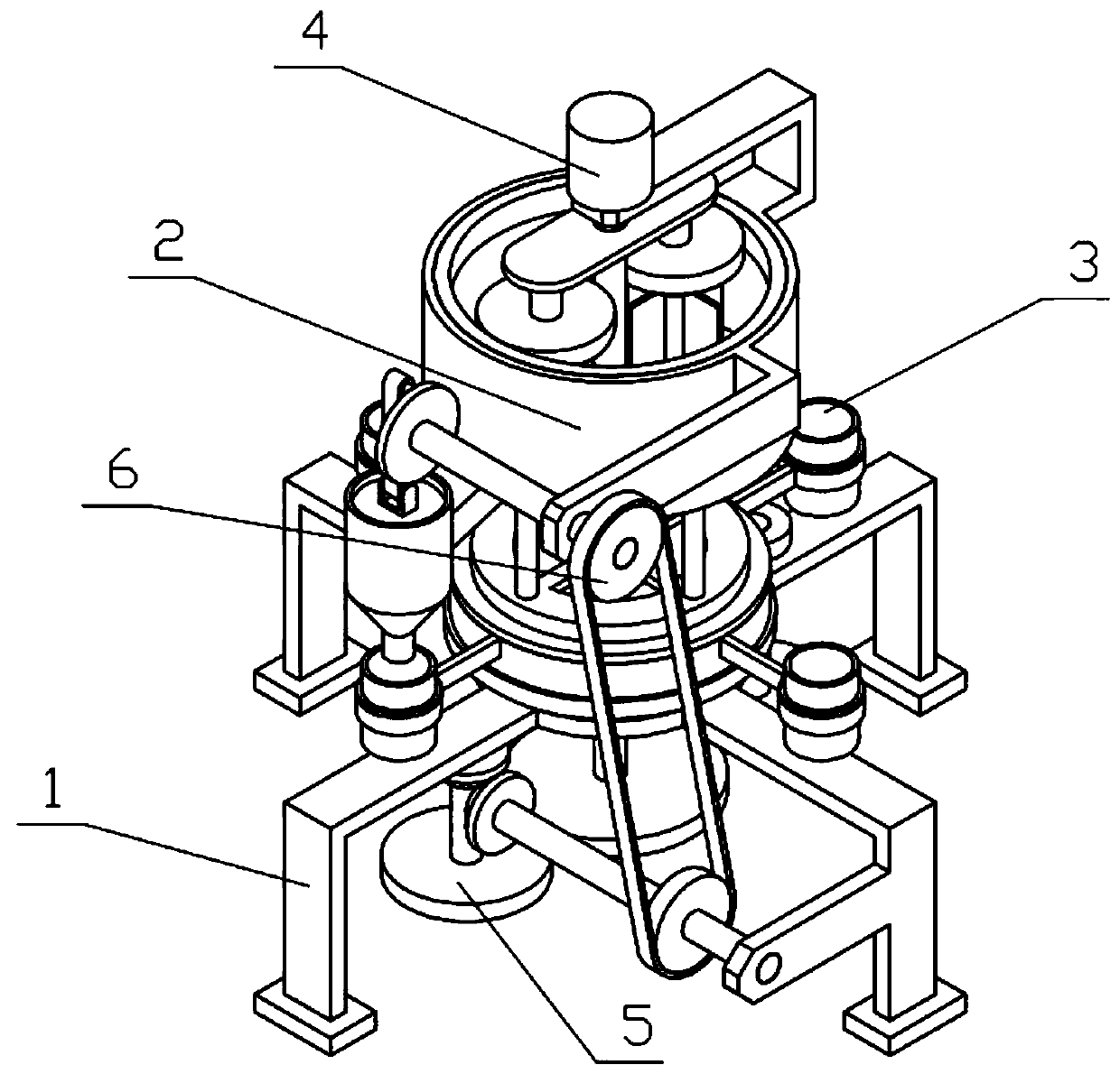
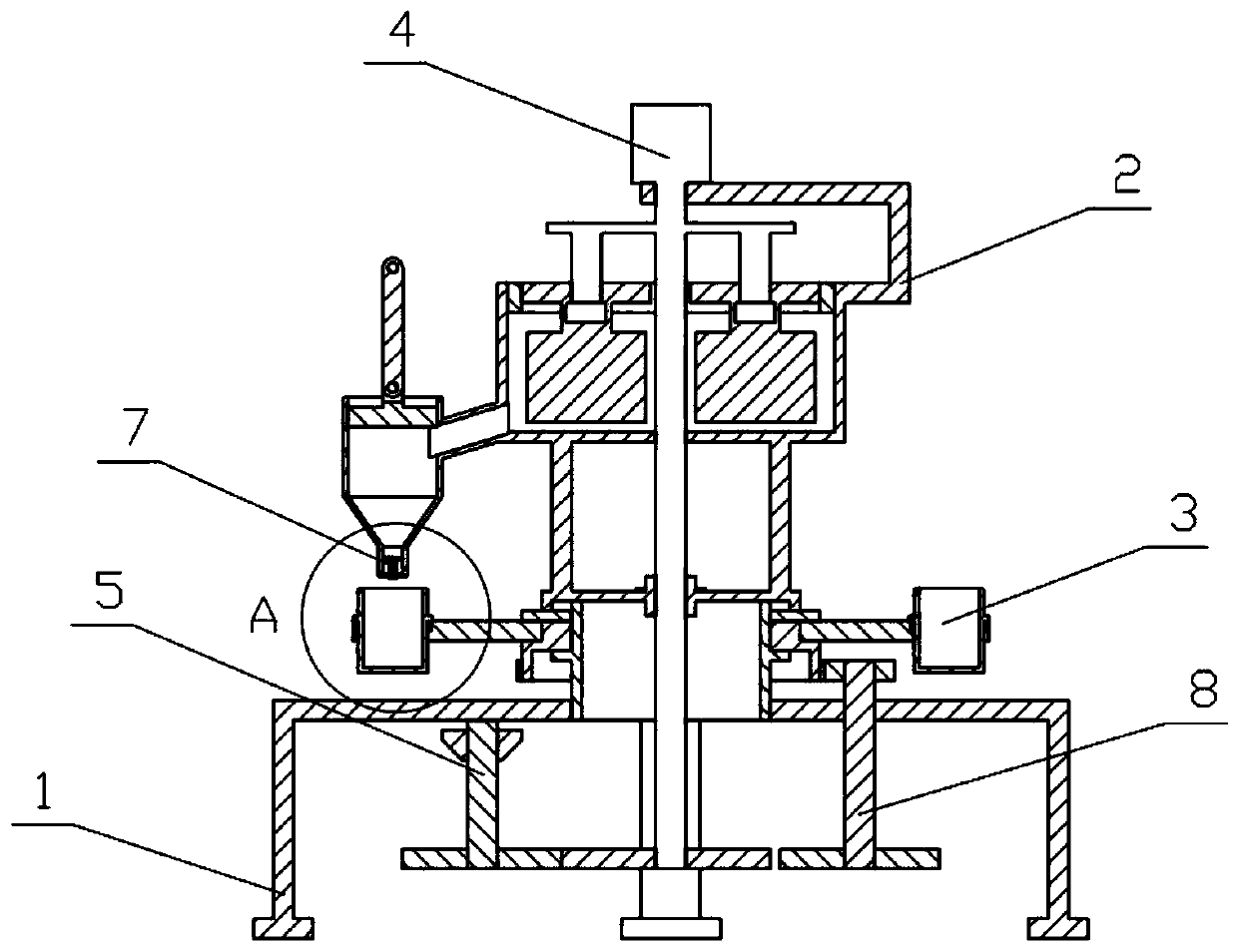
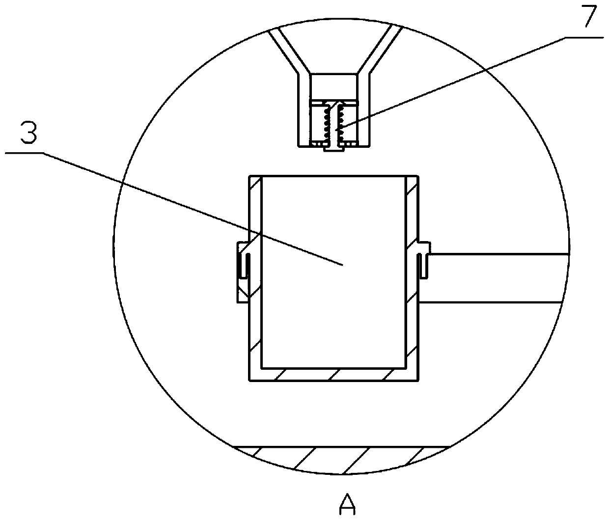
[0037] Combine below Figure 1-12Describe this embodiment, a shower gel processing system, including a processing support 1, a stirring support 2, a replacement mechanism 3, a power mechanism 4, a transmission mechanism I5, an extrusion mechanism 6, a one-way mechanism 7, and a transmission mechanism II8. The support 2 is fixedly connected to the processing support 1, the replacement mechanism 3 is rotatably connected to the processing support 1, the upper end of the power mechanism 4 is fixedly connected to the stirring support 2, the lower end of the power mechanism 4 is rotatably connected to the processing support 1, and the transmission mechanism I5 rotates Connected to the processing support 1, the transmission mechanism Ⅰ5 and the power mechanism 4 are meshed for transmission, the extrusion mechanism 6 is installed on the stirring support 2, the extrusion mechanism 6 and the transmission mechanism Ⅰ5 are connected by a belt transmission, and the extrusion mechanism 6 dri...

specific Embodiment approach 2

[0038] Combine below Figure 1-12 This embodiment will be described. This embodiment will further describe Embodiment 1. The processing bracket 1 includes a processing bracket 1 including a support ring 1-1, an installation cylinder 1-2, a support foot 1-3, and a support plate 1-4. The ring 1-1 is fixedly connected with an installation cylinder 1-2, and the supporting ring 1-1 is evenly fixedly connected with four supporting legs 1-3, and one of the supporting legs 1-3 is fixedly connected with a supporting plate 1-4.

specific Embodiment approach 3

[0039] Combine below Figure 1-12 Describe this embodiment, this embodiment will further explain the second embodiment, the stirring bracket 2 includes a mixing drum 2-1, a ring gear 2-2, a motor support plate 2-3, a rotating support plate 2-4, a connecting plate 2-5, connecting column 2-6, discharge frame 2-7 and extrusion cylinder 2-8, the upper end of the mixing cylinder 2-1 is fixedly connected with the ring gear 2-2, and the mixing cylinder 2-1 is fixedly connected with the motor The support plate 2-3 and the rotating support plate 2-4, the connection column 2-6 are fixedly connected between the connection plate 2-5 and the mixing drum 2-1, the discharge frame 2-7 is inclined, and the discharge frame 2-7 Fixedly connected to the mixing drum 2-1, the discharge rack 2-7 is connected to the mixing drum 2-1, the extrusion drum 2-8 is fixedly connected to the discharge rack 2-7, and the extrusion drum 2-8 is connected to the discharge rack 2-8. The frame 2-7 is connected, and...


PUM


Abstract

The invention relates to a shower gel processing system, a shower gel processing method and shower gel and more particularly relates to the shower gel processing system, the shower gel processing method and the shower gel. The shower gel is prepared from the following components according to the content: 30 percent of fructus gleditsiae extract, 4 to 8 percent of lauric acid, 3 to 5 percent of herba houttuyniae extract powder, 0.4 percent of osmanthus flower essence, 1.6 percent of tocopheryl acetate and the balance of de-ionized water. Different raw materials for processing the shower gel areput into a stirring barrel; the different raw materials in the stirring barrel are uniformly stirred through two stirring rods; a power mechanism drives a transmission mechanism I and a transmissionmechanism II to move intermittently; when the transmission mechanism I moves, a replacement mechanism is driven to move; when the transmission mechanism II moves, an extruding mechanism is driven to move; when the replacement mechanism moves, replacement of a storage bottle at the lower side of an extruding barrel is finished; when the extruding mechanism moves, equal amount of the shower gel is filled into the storage bottle at the lower side of the extruding barrel.

Description

technical field [0001] The present invention relates to a shower gel processing system, a processing method, and a shower gel, more specifically, a shower gel processing system, a shower gel processing method, and a shower gel. Background technique [0002] For example, the publication number CN207595364U is an automatic filling device for bagged mineral salt shower gel, which includes a frame, a hydraulic lifting cylinder, a bag cover storage box and a collection chute. The inner bottom of the frame is provided with a conveyor belt body. A bagged fixing clip is provided, a blower is installed on the inner top of the frame through a mounting seat, an air supply duct is provided at the bottom of the blower, and a shower gel storage tank is provided on one side of the blower, and the shower gel storage tank The bottom of the body is provided with a filling nozzle, one side of the shower gel storage tank is provided with a mounting frame, a rotating motor is provided in the mou...

Claims


Application Information

Patent Timeline
Patent Type & Authority Applications(China)
IPC IPC(8): B01F7/30B67C3/26B67C3/24
Inventor 魏霞
Owner 浙江英树生物科技有限公司
Why Eureka
Try Eureka