An anti-clogging garden drainage mechanism and its construction method
A drainage mechanism and anti-clogging technology, applied in drainage structures, general water supply conservation, waterway systems, etc., can solve problems such as motor leakage, foreign body blockage, and permeable plate body blockage, etc., to improve utilization, avoid water resources, and reduce labor. The effect of cleaning up Chen Ben
- Summary
- Abstract
- Description
- Claims
- Application Information
AI Technical Summary
Problems solved by technology
Method used
Image
Examples
Embodiment 1
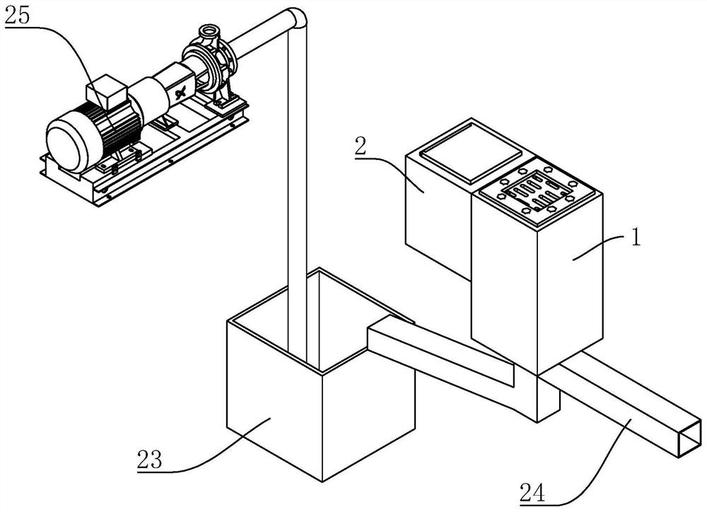
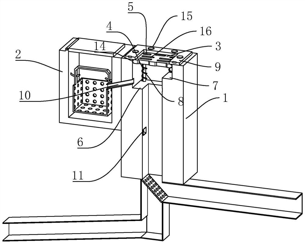
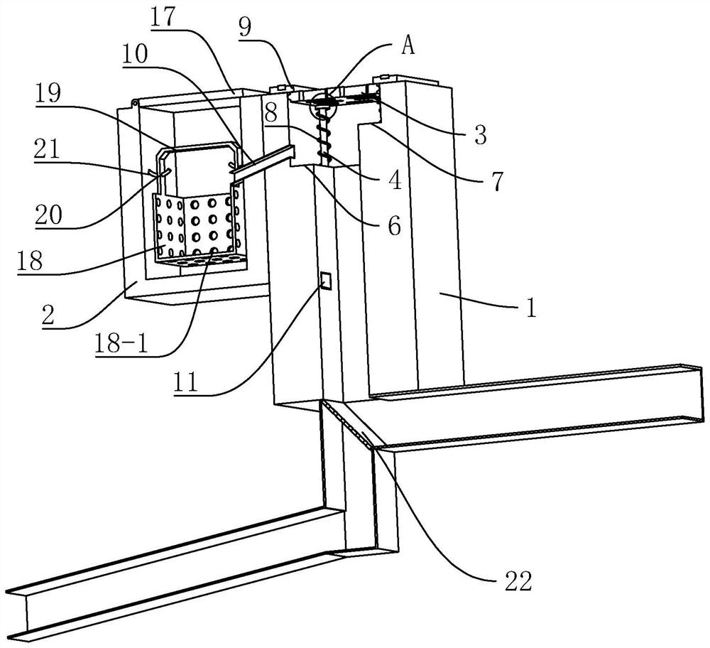
[0043] Embodiment one, a kind of garden drainage mechanism that can prevent clogging, refer to figure 1 and figure 2 , including a drain pipe 1 and a buffer box 2 located on one side of the drain pipe 1 . The section of the drainage pipe 1 is rectangular, and the two sides of the interior are recessed to form a first positioning platform 6 and a second positioning platform 7 respectively, wherein the height of the first positioning platform 6 is lower than that of the second positioning platform 7 . Two positioning rods 4 are vertically fixed on the first positioning platform 6 and the second positioning platform 7 , and a spring as an elastic member 8 is sleeved on each positioning rod 4 .
[0044] refer to image 3 and Figure 4 , a water-permeable board 3 is also installed on the drain pipe 1, and the water-permeable board 3 is sleeved on four positioning rods 4 through the waist-shaped holes 5 provided. A back-shaped limiting plate 9 is fixed on the upper end of the p...
Embodiment 2
[0049] Embodiment two, a kind of construction method of anti-clogging garden drainage mechanism, comprises:
[0050] S1, dig out a reservoir 23 on the foundation, and the foundation pit for placing the drainage pipe 1 and the buffer box 2;
[0051] S2. Connect the lower end of the drainage pipe 1 to the reservoir 23, and connect the water outlet 24 to the garden drainage system;
[0052] S3. Set the elastic member 8 on the positioning rod 4, then place the permeable plate 3 in the drain pipe 1, and finally position the limit plate 9 through the fastener 15 to position the permeable plate 3 in the drain pipe 1;
[0053] S4, the drain pipe 1 and the buffer tank 2 are communicated with each other through the discharge pipe 10 and the water pipe 11;
[0054] S5, backfilling the foundation pit.
PUM
 Abstract
Description
Claims
Application Information
 - R&D
- Intellectual Property
- Life Sciences
- Materials
- Tech Scout
- Unparalleled Data Quality
- Higher Quality Content
- 60% Fewer Hallucinations
Browse by: Latest US Patents, China's latest patents, Technical Efficacy Thesaurus, Application Domain, Technology Topic, Popular Technical Reports.
© 2025 PatSnap. All rights reserved.Legal|Privacy policy|Modern Slavery Act Transparency Statement|Sitemap|About US| Contact US: help@patsnap.com


