Method for controlling separated layer water injection by flow wave

A technology of layered water injection and flow rate, applied in layered water injection wells, using flow wave to control layered water injection field, can solve the problems of large power loss of downhole batteries, short service life of water nozzles, easy occurrence of accidental failures, etc., to reduce work The effect of reducing the amount of energy, prolonging the service life, and saving the energy consumption of the action

Active Publication Date: 2019-05-17
CHINA PETROLEUM & CHEM CORP +1
View PDF8 Cites 7 Cited by
  • Summary
  • Abstract
  • Description
  • Claims
  • Application Information

AI Technical Summary

Problems solved by technology

Regardless of the start bit and the end bit, assuming that the transmitted data is a 2-digit decimal number "46", the time required for communication is 20N. In current practical applications, it takes a long time to return data from underground to the ground. For 3,000 With a well depth of meters, it takes about 45 minutes to upload a layer of data; the flow wave presents low→high→low→high→low, and the faucet needs to operate four times, which consumes a lot of energy, and the life of the faucet is short, and the battery power in the well is depleted Big
[0005] Once the power of the downhole battery decays to a certain extent, the well must be lifted to replace the battery. The thousands of meters of pipe string need to be pulled out from the wellhead section by section. After the new battery is installed, the pipe string needs to be re-run downhole section by section. A few days, a lot of work, and prone to unexpected failures

Method used


Image

  • Method for controlling separated layer water injection by flow wave
  • Method for controlling separated layer water injection by flow wave
  • Method for controlling separated layer water injection by flow wave

Examples


Embodiment Construction

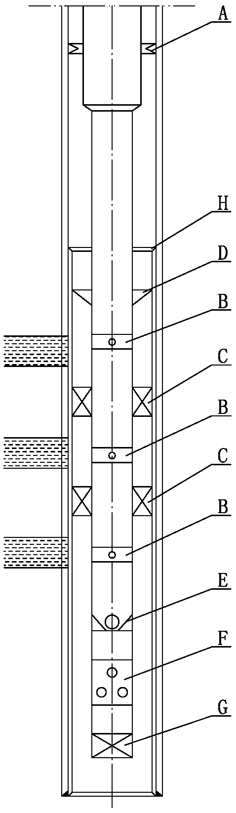
[0031] Such as figure 1 As shown, the water injection string of the present invention is inserted into the inner cavity of the small casing, the upper end of the small casing is suspended on the inner wall of the large casing by the casing hanger H, and the upper end of the water injection string extends above the small casing And it is connected with the large-diameter section of the pipe string through the variable-diameter joint, and the large-diameter section of the pipe string is fixed in the inner cavity of the large casing through the hydraulic anchor A. The position corresponding to the oil layer on the water injection pipe string is respectively equipped with an intelligent water distributor B. Intelligent water distributors B are all controlled by the ground control system. Packers C are installed between adjacent intelligent water distributors, centralizers D are installed above the top intelligent water distributors, and smart water distributors B in the bottom oil ...


PUM


Abstract

The invention relates to a method for controlling separated layer water injection by flow wave. The method comprises the following steps: mounting an intelligent water distributor corresponding to each water injection layer on a water injection pipe column, and mounting a well mouth main station controller and an intelligent water adjusting valve on a well mouth; encoding a command transmitted tothe underground by the well mouth main station controller and controlling the intelligent water adjusting valve to generate downlink flow wave; receiving and decoding the downlink flow wave by the intelligent water distributor, and controlling a water nozzle to inject water according to the command of a main station; encoding data needing to be uploaded by the intelligent water distributor and forming corresponding uplink flow wave; and receiving the uplink flow wave by a well mouth main station receiver and then decoding to acquire the needed data, wherein encoding is performed at a combination of a start bit, a data segment and an end bit, each bit of data n is represented by nT+1T time units, and 1T follows the heel of nT and presents the opposite flow state with the nT. The method hasthe encoding characteristics of changing periods and reducing action energy consumption, communication time consumption can be shortened and the water nozzle action times can be reduced.

Description

technical field [0001] The invention relates to layered water injection wells in the oil and gas field, in particular to a method for controlling layered water injection by using flow waves, and belongs to the technical field of layered water injection. Background technique [0002] Layered water injection is a technological measure to implement water injection through the isolation of the packer and the control of the water nozzle of the water distributor, so that the high, medium and low permeability formations can play the role of water injection, so as to realize the adjustment of the conflict between oilfield layers and improve the water injection sweep coefficient. [0003] At present, the commonly used water distributor is a cableless intelligent water distributor. The communication methods used by the surface device and the downhole device mainly include: decentralized communication sub-section communication or one-way flow wave communication. The decentralized commun...

Claims


Application Information

Patent Timeline
Patent Type & Authority Applications(China)
IPC IPC(8): E21B43/20E21B47/12
Inventor 白友国刘炳官任向阳朱苏青刘松林李兴龙远强
Owner CHINA PETROLEUM & CHEM CORP
Why Eureka
Try Eureka