
Heading machine dust-removing device

A technology of dust removal device and roadheader, which is applied in the direction of slitting machinery, earthwork drilling and mining, etc., which can solve the problems of reducing production efficiency, increasing roadway humidity, and rock and soil bonding into blocks, etc., to achieve low cost, reduce roadway dust, and save water. resource effect

Pending Publication Date: 2019-05-17
CHINA UNIV OF PETROLEUM (EAST CHINA)
View PDF12 Cites 3 Cited by
  • Summary
  • Abstract
  • Description
  • Claims
  • Application Information

AI Technical Summary

Problems solved by technology

[0002] At present, with the expansion of the scale of coal mining in my country and the continuous improvement of rapid excavation technology, the amount of dust produced in the excavation process of a large number of rock masses and semi-coal rock roadways is also increasing. The area where the dust is most concentrated is around the drill bit. By controlling the dust around the drill bit, the amount of dust in the entire roadway can be greatly reduced, and the probability of pneumoconiosis among the staff in the roadway can also be reduced. The form combines the dust particles floating in the air with the water mist and falls to the ground. Since the internal environment of the rock mass and semi-coal rock roadway is humid, spraying water mist in such a humid environment will increase the humidity of the roadway, resulting in rock soil in the roadway. Sticking into blocks is not conducive to outward transportation, and it is easy to cause equipment failure and reduce production efficiency

Method used


Image

  • Heading machine dust-removing device
  • Heading machine dust-removing device
  • Heading machine dust-removing device

Examples


Embodiment Construction

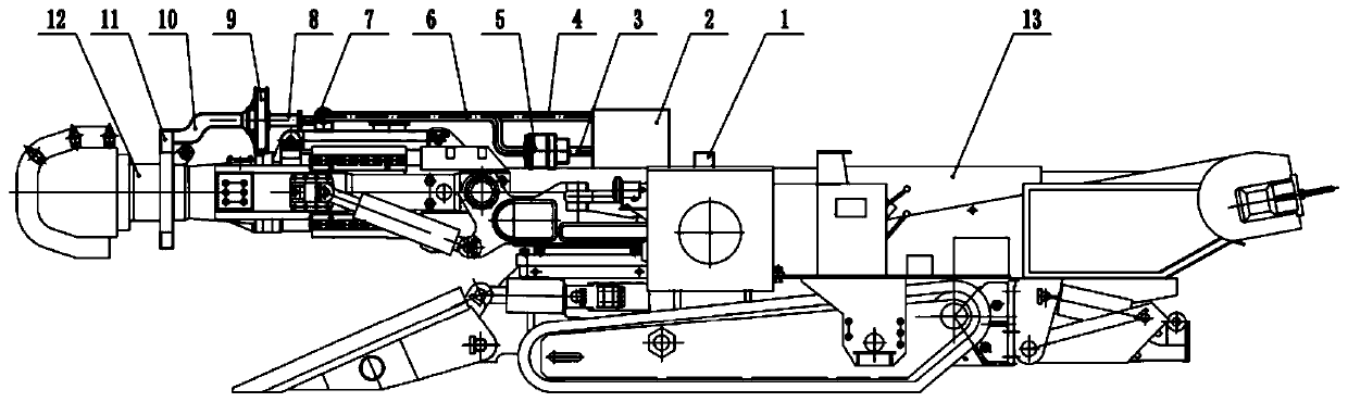
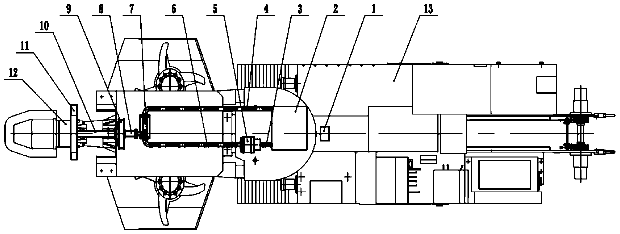
[0015] Attached below figure 1 ~ attached Figure 5 The present invention is described in detail below.

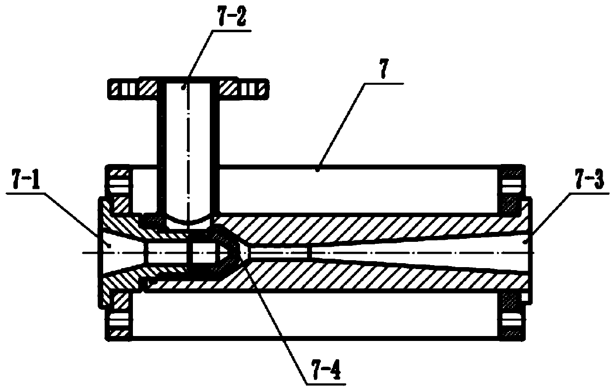
[0016] Such as Figure 1~5 As shown, the present invention includes a frame 13 and a cutting part 12. The cutting part 12 is in the shape of a cylinder that is thin at the front and thick at the back. The dust collector 11 is provided with four sets of dust suction holes 11-1 at the end close to the drill bit, and a dust collection pipe 10 is provided at the end far away from the drill bit. Connected; the upper end surface of the frame 13 is provided with an induced draft fan 9, an air pipe 8, a jet diverter 7, a water inlet pipe 6, an outlet pipe 4, a high-pressure water pump 5, a suction pipe 3, a sedimentation filter water tank 2 and The control box 1, the air inlet of the induced draft fan 9 are fixedly connected to the dust collection pipe 10, the air outlet is fixedly connected to the air pipe 8, and the jet diverter 7 includes an air inlet 7-2, a water inlet 7-1,...


PUM


Abstract

The invention relates to the technical field of underground coal mine tunneling working face heading equipment, in particular to a heading machine dust-removing device. The heading machine dust-removing device comprises a cutting part and a machine frame; the cutting part is in sleeving connection with an annular hollow dust collector; and an induced draft fan, a gas conveying pipe, a jet drainageapparatus, a water inlet pipe, a water outlet pipe, a high-pressure water pump, a water pumping pipe, a settling and filtering water tank and a control box are arranged on the upper end face of the machine frame sequentially from left to right. According to the technical scheme, the structural design is reasonable; dust can be absorbed in the jet drainage apparatus through conversion of velocityenergy and pressure energy of water flow by the jet drainage apparatus; the dust and spray are fused into one by controlling the pressure of the high-pressure water pump; by using the air suction capacity of the induced draft fan, the dust can be absorbed in the induced draft fan rapidly, and the dust in a laneway is reduced under the condition of not increasing the humidity of the laneway; the mixed liquid is settled and filtered as well as recycled by the settling and filtering water tank; and the heading machine dust-removing device is particularly suitable for underground coal mine and hasgood popularization and application prospect.

Description

technical field [0001] The technical proposal relates to the technical field of tunneling equipment for tunneling working faces in underground coal mines, in particular to a dust removal device for tunneling machines. Background technique [0002] At present, with the expansion of the scale of coal mining in my country and the continuous improvement of rapid excavation technology, the amount of dust produced in the excavation process of a large number of rock masses and semi-coal rock roadways is also increasing. The area where the dust is most concentrated is around the drill bit. By controlling the dust around the drill bit, the amount of dust in the entire roadway can be greatly reduced, and the probability of pneumoconiosis among the staff in the roadway can also be reduced. The form combines the dust particles floating in the air with the water mist and falls to the ground. Since the internal environment of the rock mass and semi-coal rock roadway is humid, spraying water...

Claims


Application Information

Patent Timeline
Patent Type & Authority Applications(China)
IPC IPC(8): E21C35/22
Inventor 赵军友时敏张亚宁田亚敏毕晓东董亚飞
Owner CHINA UNIV OF PETROLEUM (EAST CHINA)
Learn More