Eureka AIR delivers breakthrough ideas for toughest innovation challenges, trusted by R&D personnel around the world.

Conveying and transporting device for foundational detonator

A technology of basic detonators and conveying devices, which is applied in the direction of weapon accessories, blasting tubes, fuzes, etc., can solve the problems of large turnover stock, poor safety, and low level of operation technology on site, so as to reduce turnover stock, improve production efficiency and reliability, The effect of improving safety

Pending Publication Date: 2019-05-17
北京凯米迈克科技有限公司
View PDF0 Cites 4 Cited by
  • Summary
  • Abstract
  • Description
  • Claims
  • Application Information

AI Technical Summary

Problems solved by technology

[0006] At present, in the assembly and production process of industrial detonators, there are safety problems such as manual operation and transfer of basic detonators and their molds or carriers, and large turnover stocks on site, and the disadvantages of low operating technology level, poor safety, and low efficiency. The purpose of the present invention It is to provide a basic detonator transfer and conveying device, which can automatically take out 50 or 100 rounds of whole-model basic detonators from devices such as a transfer belt or a temporary storage explosion-proof box, and automatically lift the whole-model basic detonators to the workbench. At the highest operating height, the whole model base detonator is placed in a fixed loading position that is convenient to pick and place, so that it is easy to take out the base detonator for the assembly and production of industrial detonators

Method used


Image

  • Conveying and transporting device for foundational detonator
  • Conveying and transporting device for foundational detonator
  • Conveying and transporting device for foundational detonator

Examples


Embodiment Construction

[0028] The present invention will be described in further detail below in conjunction with the accompanying drawings and specific embodiments.

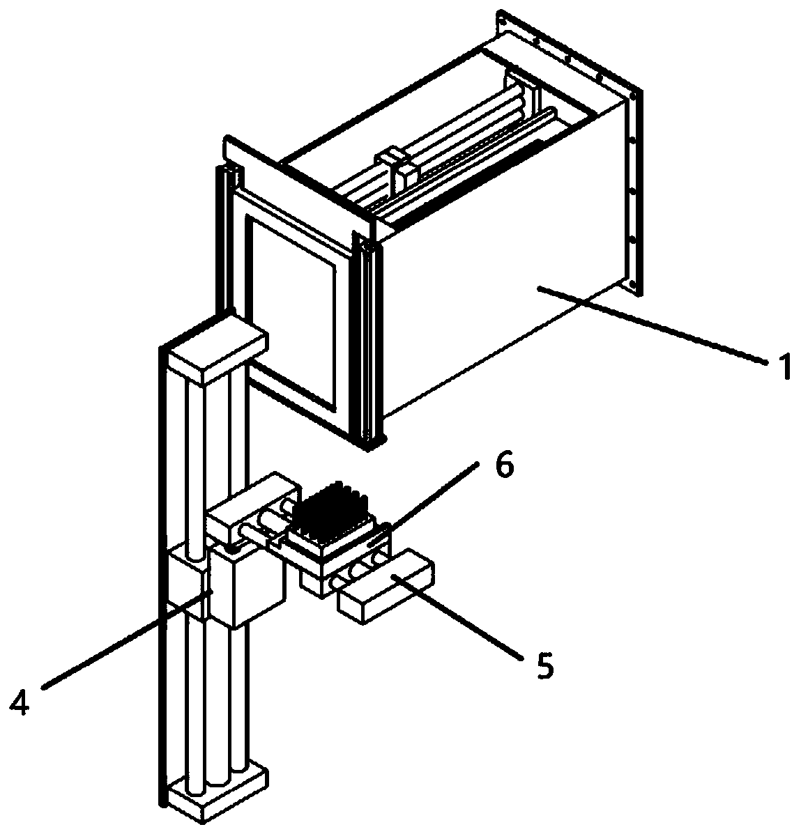
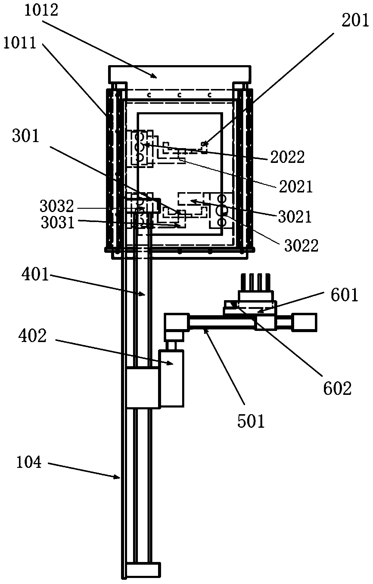
[0029] Such as Figure 1-5 As shown, a basic detonator delivery device includes an explosion-proof box 1, a feeding module, an ejection module, a lifting module 4, a translation module 5 and a positioning module 6; wherein, the explosion-proof box 1 includes a door opening cylinder 1011, an explosion-proof Damper 1012, explosion-proof plate 102, explosion vent 103, box extension plate 104; feeding module includes feeding slide rail 201, feeding pull block 2021, feeding pull block cylinder 2022; ejection module includes ejection slide rail 301, ejection hook 3021, ejection hook cylinder 3022, ejection block 3031, ejection block cylinder 3032; lift module 4 includes main lift cylinder 401, auxiliary lift cylinder 402; translation module 5 includes translation cylinder 501; The positioning module 6 includes a base detonator mold positio...


PUM


Abstract

The invention relates to the field of civilian-used explosive material production and a conveying and transporting device for a foundational detonator. The conveying and transporting device for the foundational detonator comprises an anti-explosion box body, a feeding module, a mold unloading module, a lifting module, a translation module and a positioning module; when mold unloading is conducted,the lifting module moves to the height of the position of the mold unloading module, the translation module drives an empty mold in the positioning module to horizontally move to the position of themold unloading module, and under the action of the mold unloading module , the empty mold moves to a circumscribed empty mold transporting belt; when feeding is conducted, a mold preparation foundational detonator mold on a circumscribed foundational detonator transporting belt enters the feeding module, meanwhile the lifting module moves to the height of the position of the feeding module, the translation module drives the empty mold in the positioning module to horizontally move to the position of the feeding module, the feeding module drives the mold preparation foundational detonator moldto move into the positioning module, and then the lifting module moves to the fixed feeding position of an operation table. Continuous, automatic, high-reliability and high-safety conveying and transporting of the mold preparation foundational detonator are achieved.

Description

technical field [0001] The invention relates to the field of civil blasting equipment production, in particular to a lifting and horizontal transfer conveying device for basic detonators and their molds or carriers. Background technique [0002] In the assembly and production process of industrial detonators, the basic detonators need to be loaded into special molds or carriers and sent to each assembly station. The current transfer production process manually transfers the basic detonators to the assembly personnel's station, and then the assembly operation Personnel assemble the basic detonator and ignition parts into industrial electric detonator or electronic detonator or nonel detonator. Since the operating speed of the assembler and the transfer volume of the transfer personnel need to be coordinated and matched, the transfer personnel generally place a large number of basic detonators (according to safety management requirements, no more than 320 rounds on the table o...

Claims


Application Information

Patent Timeline
Patent Type & Authority Applications(China)
IPC IPC(8): F42C19/12F42B3/195
Inventor 李明安柳勤张连壮张理农李纯荣
Owner 北京凯米迈克科技有限公司
Why Eureka
Eureka Blog
Learn More