Automatic focusing binocular camera calibration and depth calculation method

A binocular camera and auto-focus technology, applied in the field of optical measurement, camera manufacturing, and computer vision, can solve problems such as changes in lens calibration parameters, achieve the effects of reducing production costs, increasing production, and enhancing product competitiveness

Pending Publication Date: 2019-05-17
像工场(深圳)科技有限公司
View PDF8 Cites 12 Cited by
  • Summary
  • Abstract
  • Description
  • Claims
  • Application Information

AI Technical Summary

Problems solved by technology

[0007] The purpose of the present invention is to provide an auto-focus binocular camera calibration and depth calculation method to solve the problem of calibration parameter changes caused by changes in the position of the lens in the lens barrel

Method used


Image

  • Automatic focusing binocular camera calibration and depth calculation method
  • Automatic focusing binocular camera calibration and depth calculation method
  • Automatic focusing binocular camera calibration and depth calculation method

Examples


specific Embodiment

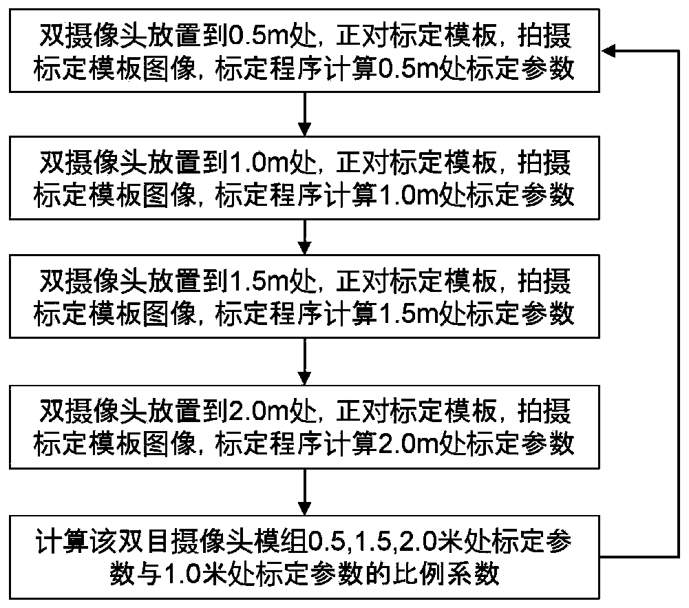
[0111] Figure 2A , Figure 2B , Figure 2C , Figure 2D It is the structural diagram of the pre-calibration device during the trial production of the binocular camera. Place a 2D plane at each of the four distances (the calibration distance can be appropriately selected according to the requirements of the subsequent binocular camera application, production line time requirements, and laboratory equipment size requirements. Here, the four distances are taken as an example, the same below). Calibration template: 0.5, 1.0, 1.5, 2.0 meters. The binocular camera module is placed in the position facing the calibration template in turn, that is, the optical axis of the binocular camera is perpendicular to the calibration template, the camera takes a static picture, and the calibration algorithm calculates the camera calibration parameters. After the distance calibration is completed, the camera moves to the next distance calibration position. After the four distance calibration...

Embodiment 1

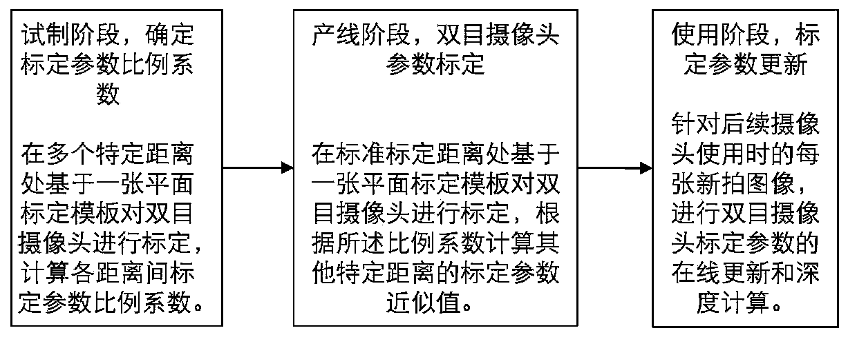
[0114] This embodiment is divided into three stages: trial production stage, production line stage and use stage. The following are detailed implementation steps:

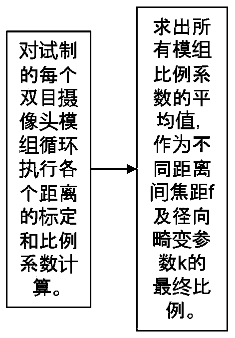
[0115] The first stage: the trial production stage, use 50 binocular camera modules to calibrate at four distances (0.5, 1.0, 1.5, 2.0 meters), and calculate the calibration parameter ratio coefficient between each distance

[0116] The first step: place the module to be tested to the calibration template at 0.5m, take a picture of the calibration template, and the calibration program calculates the calibration parameters at 0.5m

[0117] Obtain a calibration template image, obtained by shooting the calibration template; (corresponding to S1)

[0118] Calibration templates are generally repeated patterns with fixed spacing, such as black and white checkerboard calibration templates, equidistant solid circle array calibration templates, etc. In this example, only one calibration template image needs to be taken fo...


PUM


Abstract

The invention provides an automatic focusing binocular camera calibration method. The automatic focusing binocular camera calibration method comprises the following steps: A1, obtaining a calibrationtemplate image from a standard calibration distance; A2, analyzing and processing a single calibration template image shot at the standard calibration distance, and acquiring calibration parameters ofthe binocular camera at the standard calibration distance through calculation; A3, calculating calibration parameter approximate values of the plurality of specific calibration distances according toa pre-obtained proportionality coefficient of the calibration parameters of the binocular camera module at the plurality of specific calibration distances and the calibration parameters of the standard calibration distance, wherein the calibration parameters of the binocular camera module are measured at the standard calibration distance; And A4, taking the approximate value as a production linecalibration result of the automatic focusing binocular camera. When the binocular camera is used, more accurate calibration parameters and more accurate depth values are obtained through online updating and iteration of the calibration parameters based on the currently photographed image.

Description

technical field [0001] The invention relates to the fields of computer vision, optical measurement and camera manufacturing, in particular to a binocular camera calibration method and device on a production line and a depth calculation method. Background technique [0002] Autofocus refers to a built-in function of the camera that automatically focuses on the subject and makes the image clear through electronic and mechanical devices. Due to the characteristics of accurate focusing and convenient operation, cameras with autofocus function are widely used in more and more industries, including smart phones, drones, video surveillance and other fields. [0003] On the other hand, camera applications are entering the 3D era based on binocular and multi-eye cameras from 2D. For example, in the mobile phone industry, the optical zoom function is realized through the combination of wide-angle camera and telephoto camera, or the combination of black and white and color cameras is ...

Claims


Application Information

Patent Timeline
IPC IPC(8): G06T7/80
CPCY02P90/30
Inventor 蔡瑜娄磊王飞汪洋
Owner 像工场(深圳)科技有限公司
Why Eureka
Try Eureka