Fast installation fixture for photovoltaic module

A technology of photovoltaic modules and installation fixtures, which is applied to the support structure of photovoltaic modules, photovoltaic modules, photovoltaic power generation, etc., which can solve the problems of poor applicability and inability to install photovoltaic modules of different thicknesses, and achieve good applicability

Pending Publication Date: 2019-05-17
ARCTECH SOLAR HLDG CO LTD
View PDF1 Cites 8 Cited by
  • Summary
  • Abstract
  • Description
  • Claims
  • Application Information

AI Technical Summary

Problems solved by technology

[0003] Since photovoltaic modules have various specifications, it is necessary to design installation fixtures of corresponding sizes corresponding to photovoltaic modules of different specifications, and install photovoltaic modules on the main beam through the installation fixtures, such as US patent US 10069455, MOUNTINGBRACKETASSEMBLIES AND METHODS, which discloses An installation fixture for fixing photovoltaic modules on the main beam, but it cannot install photovoltaic modules of different thicknesses, and only one specification of photovoltaic modules is applicable, resulting in the need to make pressure plates of different heights when installing photovoltaic modules of different thicknesses, which has poor applicability good

Method used


Image

  • Fast installation fixture for photovoltaic module
  • Fast installation fixture for photovoltaic module
  • Fast installation fixture for photovoltaic module

Examples


Embodiment 1

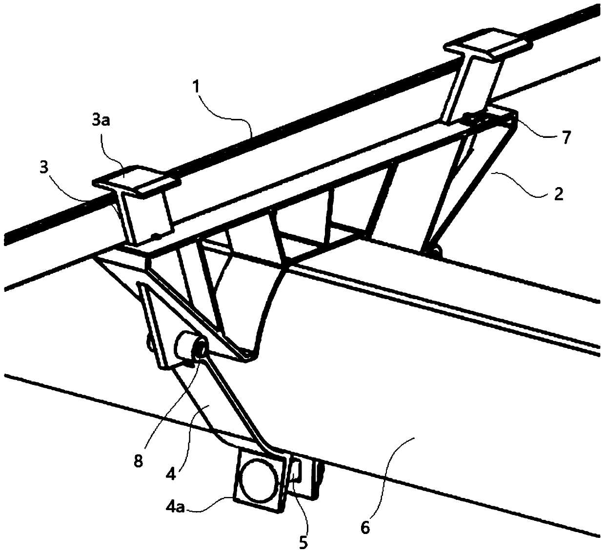
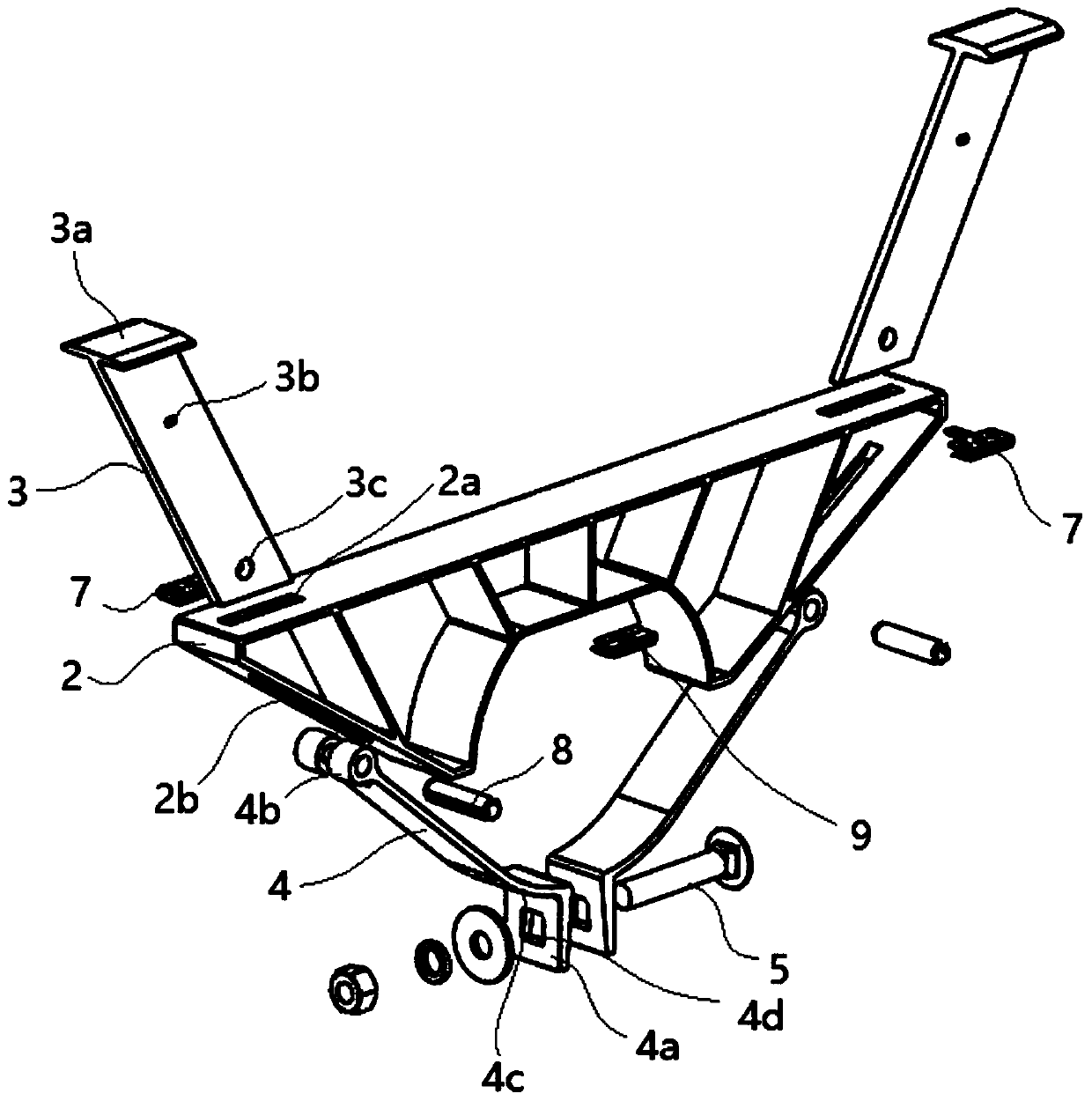
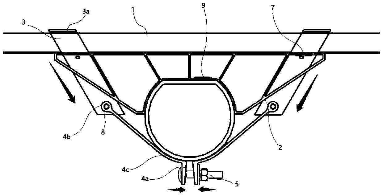
[0045] like Figure 1 to Figure 9 As shown, Embodiment 1 discloses a specific implementation of a quick installation fixture for photovoltaic modules, which can quickly install photovoltaic modules 1 of different thicknesses on the main beam 6 with a D-shaped cross-sectional shape. The board and the flat plate are composed of a purlin 2 placed on the upper end of the main beam 6, two pressing blocks 3 and two connecting plates 4. Specifically, the purlin 2 is placed on the flat plate of the main beam 6, and the purlin 2 is in the form of Arch bridge shape.

[0046] like figure 1 and Figure 4 As shown, along the extension direction perpendicular to the main girder 6, the two ends of the upper end surface of the purlin 2 are symmetrically provided with the first chute hole 2a, and the two ends of the lower end surface of the purlin 2 are symmetrically provided with the second chute hole 2b , the first chute hole 2a and the second chute hole 2b on the same side of the purlin ...

Embodiment 2

[0055] like Figure 1 to Figure 14 As shown, Embodiment 2 discloses another specific implementation of a quick installation fixture for photovoltaic modules, which can quickly install photovoltaic modules 1 of different thicknesses on the main beam 6 with a D-shaped cross-sectional shape. The main beam 6 consists of a circle The arc plate is composed of a flat plate, which specifically includes: a purlin 2 placed on the upper end of the main beam 6, two pressing blocks 3 and two connecting plates 4, specifically, the purlin 2 is placed on the flat plate of the main beam 6, and the purlin 2 In the shape of an arch bridge.

[0056] like figure 1 and Figure 4 As shown, along the extension direction perpendicular to the main girder 6, the two ends of the upper end surface of the purlin 2 are symmetrically provided with the first chute hole 2a, and the two ends of the lower end surface of the purlin 2 are symmetrically provided with the second chute hole 2b , the first chute ho...

Embodiment 3

[0067] like Figure 1 to Figure 14 As shown, Embodiment 3 discloses another specific implementation of a quick installation fixture for photovoltaic modules, which can quickly install photovoltaic modules 1 of different thicknesses on the main beam 6 with a D-shaped cross-sectional shape. The main beam 6 is formed by a circle The arc plate is composed of a flat plate, which specifically includes: a purlin 2 placed on the upper end of the main beam 6, two pressing blocks 3 and two connecting plates 4, specifically, the purlin 2 is placed on the flat plate of the main beam 6, and the purlin 2 In the shape of an arch bridge.

[0068] like figure 1 and Figure 4 As shown, along the extension direction perpendicular to the main girder 6, the two ends of the upper end surface of the purlin 2 are symmetrically provided with the first chute hole 2a, and the two ends of the lower end surface of the purlin 2 are symmetrically provided with the second chute hole 2b , the first chute h...


PUM


Abstract

The invention discloses a fast installation fixture for a photovoltaic module. The fast installation fixture comprises a purlin, two pressing blocks and two connecting plates, wherein the purlin is placed at the upper end of a main beam, wherein first chute holes are symmetrically formed in the two ends of the upper end face of the purlin along the extension direction perpendicular to the main beam; second chute holes are symmetrically formed in the two ends of the lower end face of the purlin; the first chute holes and the second chute holes in the same side of the purlin constitute chute channels; the first ends of the pressing blocks are provided with clamping parts for pressing the photovoltaic module; the pressing blocks are inserted into the chute channels, and the second ends of thepressing blocks incline towards the main beam; the pressing blocks correspond to the chute channels one by one; the first ends of the connecting plates are rotationally connected with the second endsof the pressing blocks extending out the chute channels on the side; and the second ends of the two connecting plates are connected by a distance adjustment structure. The fast installation fixture can install photovoltaic modules with different thickness on the main beam, and has wider applicability.

Description

technical field [0001] The invention relates to the field of photovoltaic module installation structure design, in particular to a quick installation fixture for photovoltaic modules. Background technique [0002] Photovoltaic power generation is a technology that directly converts light energy into electrical energy by using the photovoltaic effect at the semiconductor interface. It is mainly composed of three parts: photovoltaic modules, controllers and inverters. The photovoltaic tracking system tracks the movement of the sun in real time and directs sunlight to the photovoltaic modules, thereby increasing the amount of solar radiation received by the photovoltaic modules and increasing the overall power generation. [0003] Since photovoltaic modules have various specifications, it is necessary to design installation fixtures of corresponding sizes corresponding to photovoltaic modules of different specifications, and install photovoltaic modules on the main beam throug...

Claims


Application Information

Patent Timeline
Patent Type & Authority Applications(China)
IPC IPC(8): H02S20/30H02S20/00H02S40/00F24S25/636
CPCY02E10/47Y02E10/50
Inventor 蔡浩于鹏晓李健民
Owner ARCTECH SOLAR HLDG CO LTD
Why Eureka
Try Eureka