
Chemical engineering filter can

A filter tank and chemical technology, which is applied in the fields of filtration and separation, mobile filter element filters, chemical instruments and methods, etc., can solve the problems of difficult cleaning or removal of the filter tank, clogging of the filter device, etc., and achieve the effect of improving the filtering effect.

Active Publication Date: 2019-05-21
苏州吉态来胺生物科技有限公司
View PDF7 Cites 4 Cited by
  • Summary
  • Abstract
  • Description
  • Claims
  • Application Information

AI Technical Summary

Problems solved by technology

[0004] In order to make up for the deficiencies of the prior art, the present invention proposes a filter tank for chemical industry, which is mainly used to solve the problem that the existing filter tank is difficult to clean up in time or remove the filtered impurities, which makes the filter device prone to clogging

Method used


Image

  • Chemical engineering filter can
  • Chemical engineering filter can
  • Chemical engineering filter can

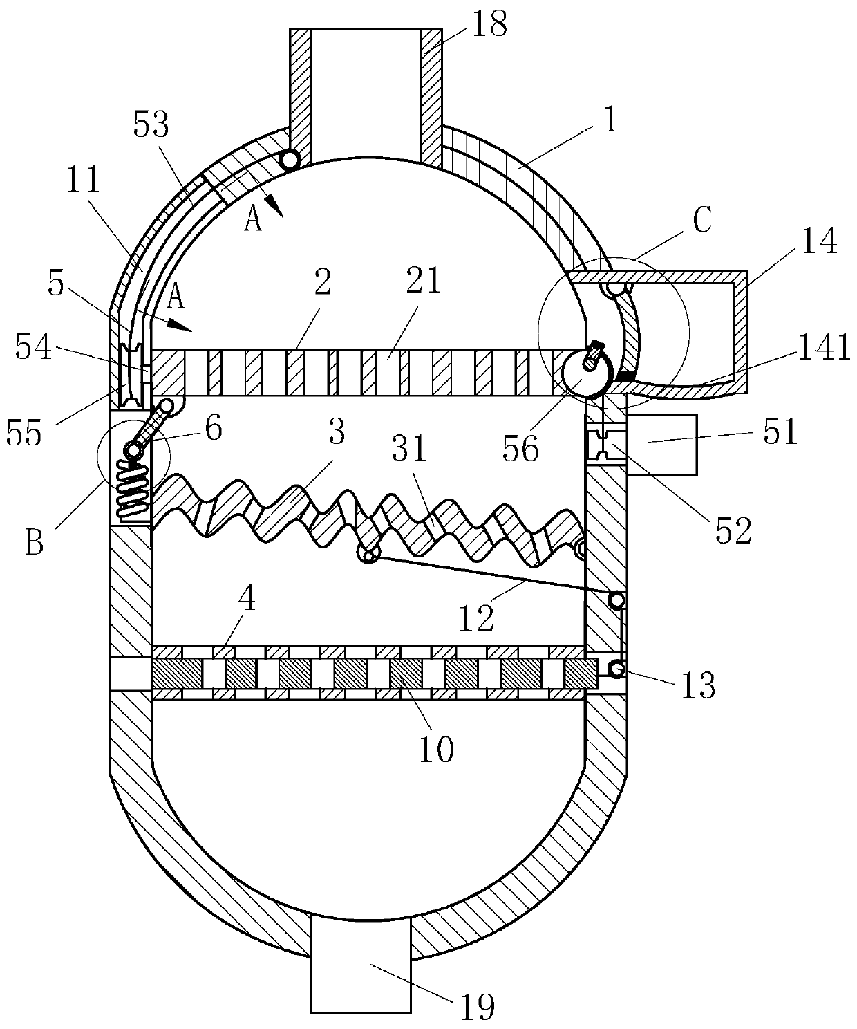
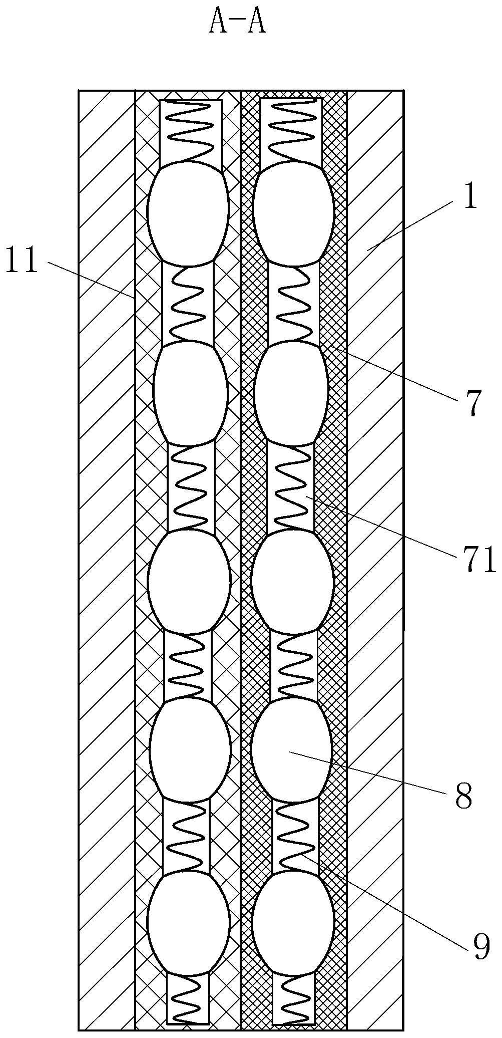
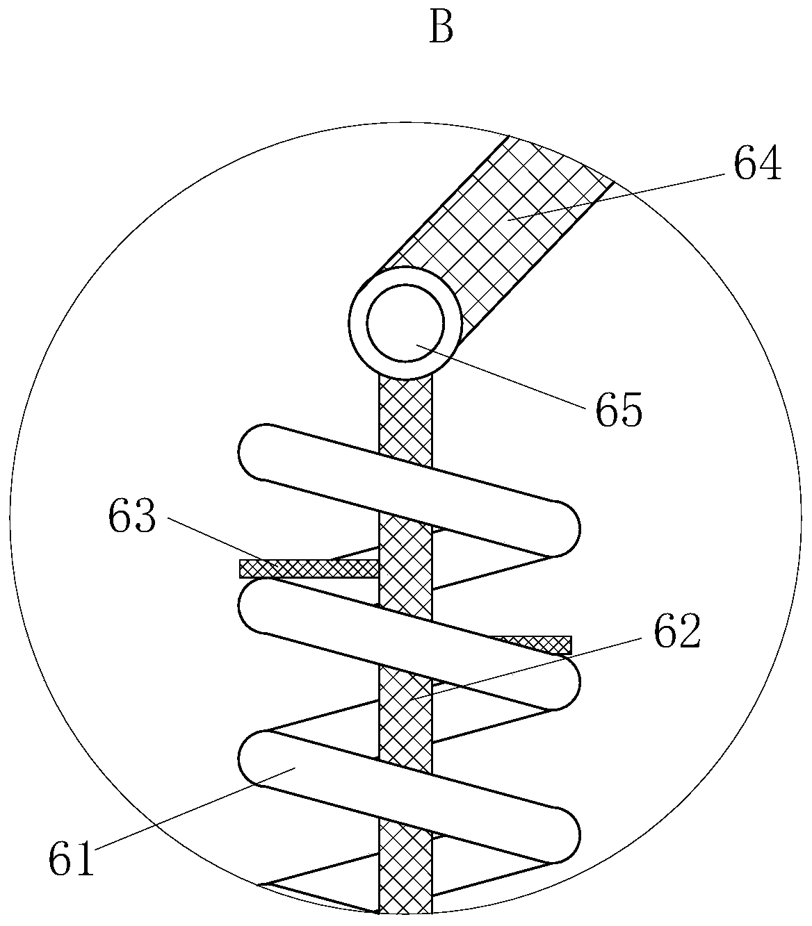
Examples


Embodiment Construction

[0023] use Figure 1-Figure 5 A chemical filter tank according to an embodiment of the present invention will be described as follows.

[0024] Such as figure 1As shown, a filter tank for chemical industry according to the present invention includes an outer tank body 1; a first filter plate 2, a corrugated metal plate 3 and a second filter plate 4 are arranged in the outer tank body 1, and the outer tank body There is a sliding groove 11 on the upper side of the body 1; the first filter plate 2 is arranged on the upper end of the outer tank body 1 through the swing unit 5, and a first filter hole 21 is opened on the first filter plate 2; the corrugated The metal plate 3 is connected to the lower end of the first filter plate 2 through the shaking unit 6, and the corrugated metal plate 3 is provided with a second filter hole 31; the third filter plate is arranged at the lower end of the corrugated metal plate 3, and the second filter plate 4 is provided with a third filter h...


PUM


Abstract

The invention belongs to the technical field of chemical engineering equipment, and particularly relates to a chemical engineering filter can. The can comprises an outer can body; the outer can body is internally provided with a first filtering plate, a corrugated metal plate and a second filtering plate; the first filtering plate is arranged on the upper end of the inside of the outer can body through a swing unit, and a first filtering hole is formed in the first filtering plate; the corrugated metal plate is connected to the lower end of the first filtering plate through a shaking unit, anda second filtering hole is formed in the corrugated metal plate; a third filtering plate is disposed on the lower end of the corrugated metal plate, and a third filtering hole is formed in the secondfiltering plate; though the first filtering plate and the corrugated metal plate, when the first filtering plate is swung, the corrugated metal plate is driven to shake by the shaking unit, debris ofexcessively large volumes are filtered and collected at the end of the first filtering plate, and the corrugated metal plate is subjected to secondary filtration in a fluid to prevent a particulate material from accumulating on the first filtering plate and the corrugated metal plate and affecting the filtering effect.

Description

technical field [0001] The invention belongs to the technical field of chemical equipment, in particular to a filter tank for chemical industry. Background technique [0002] In the chemical production process, the filtration method is often used to force the fluid in the liquid-solid or gas-solid mixture to pass through the porous filter medium, and the suspended solid particles in it are intercepted, so as to realize the separation of the mixture. Especially for sewage treatment in chemical production, in order to remove impurities, a filter cartridge filter medium is often placed between the inlet and the outlet. [0003] But the traditional filter tank can only play a simple filtering role, and the filtering effect is not obvious. When the filter tank is used for a long time, the filter material will accumulate. When the filter material in the filter tank is not cleaned and cleaned in time Replacement, it is easy to make the placed filter device prone to clogging, and t...

Claims


Application Information

Patent Timeline
Patent Type & Authority Applications(China)
IPC IPC(8): B01D33/03B01D33/41B01D33/76B01D33/80
Inventor 不公告发明人
Owner 苏州吉态来胺生物科技有限公司
Learn More