Crushing mechanism in concrete crushing machine

A pulverizing mechanism and pulverizer technology, which is applied in the direction of separating solids from solids with airflow, magnetic separation, solid separation, etc., can solve the problems of poor concrete pulverization effect and slow pulverization efficiency, and achieve fast pulverization speed and good effect , Improve the effect of crushing efficiency

Active Publication Date: 2019-05-21
淮北金辉绿建科技有限责任公司
View PDF7 Cites 14 Cited by
  • Summary
  • Abstract
  • Description
  • Claims
  • Application Information

AI Technical Summary

Problems solved by technology

[0005] The purpose of the present invention is to solve the problems of poor concrete crushing effect and slow crushing efficienc

Method used


Image

  • Crushing mechanism in concrete crushing machine
  • Crushing mechanism in concrete crushing machine
  • Crushing mechanism in concrete crushing machine

Examples


Example Embodiment

[0025] The following are specific embodiments of the present invention combined with the accompanying drawings to further describe the technical solutions of the present invention, but the present invention is not limited to these embodiments.

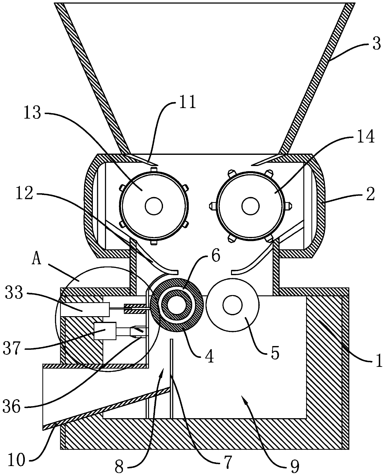
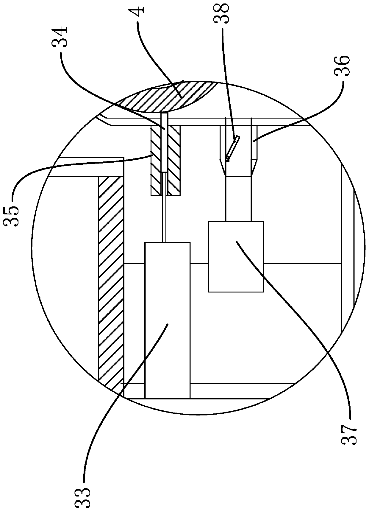
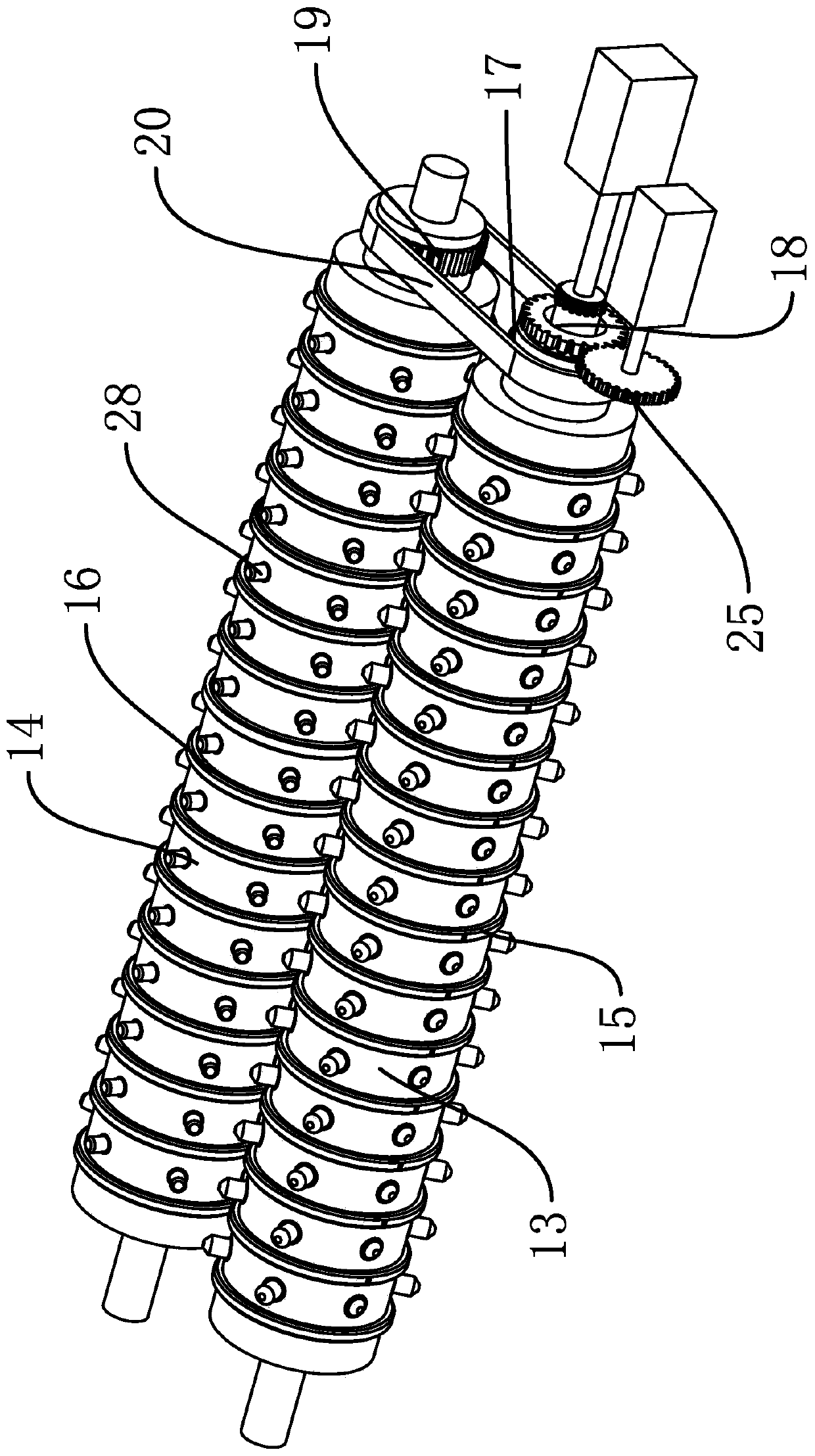
[0026] Such as Figure 1 to Figure 7 As shown, a concrete crusher includes a return box 1, a crush box 2 and a feed hopper 3. The crush box 2 is fixed on the return box 1, the feed hopper 3 is fixed on the crush box 2, and the crush box 2 is inside A crushing mechanism for rapid crushing of reinforced concrete is fixed. The lower part of the crushing box 2 is provided with a crushing roller 4 and a crushing roller 5. The crushing roller 4 and the crushing roller 5 are driven to rotate by a driving mechanism. The crushing roller 4 is provided with Electromagnet 6, a partition 7 is fixed in the return box 1, and the partition 7 separates the return box 1 into a return channel 8 for metal recovery and a recovery chamber 9 for crushed stone r...


PUM


Abstract

The invention provides a crushing mechanism in a concrete crushing machine, and belongs to the technical field of buildings. The technical problems that the existing concrete crushing effect is poor,and the existing crushing efficiency is low are solved. According to the crushing mechanism in the concrete crushing machine, the crushing machine comprises a material return box, a crushing box and afeeding hopper, the crushing box is fixed to the material return box, and the feeding hopper is fixed to the crushing box; and the crushing mechanism comprises a first crushing roll and a second crushing roll, the first crushing roll and the second crushing roll are rotatably arranged in the crushing box and adjacently arranged, a plurality of first crushing rings are fixed to the first crushingroll, a plurality of second crushing rings are fixed to the second crushing roll, a first gear and a second gear are coaxially fixed to the first crushing roll, a third gear is coaxially fixed to thesecond crushing roll, the first gear and the third gear are sleeved with a chain, and the second gear is connected with a driving assembly used for driving the second gear to rotate. The crushing mechanism in the concrete crushing machine has the advantages that the concrete crushing effect is good, and the crushing efficiency is high.

Description

technical field [0001] The invention belongs to the technical field of construction, in particular to a pulverizing mechanism in a concrete pulverizer. Background technique [0002] Compared with concrete, the tensile strength of steel bars is very high, generally above 200MPa. Therefore, people usually add reinforcing materials such as steel bars to concrete to work with it. The steel bars bear the tensile force, and the concrete bears the compressive stress. [0003] Secondly, there is a good bond between the steel bar and the concrete. Sometimes the surface of the steel bar is also processed into ribs with intervals (called deformed steel bar) to improve the mechanical engagement between the concrete and the steel bar. However, this is still not enough to transmit the steel bar and the steel bar. When the tension between the concrete, the end of the steel bar is usually bent up with a 180-degree hook. [0004] Although the firmness of reinforced concrete has been greatly...

Claims


Application Information

Patent Timeline
IPC IPC(8): B02C21/00B02C4/02B02C4/28B02C4/30B02C4/40B02C4/42B02C23/14B02C23/20B03C1/30B03C1/26B07B4/02
Inventor 不公告发明人
Owner 淮北金辉绿建科技有限责任公司
Why Eureka
Try Eureka