A rapid punching device for auto parts

A technology for auto parts and punching devices, which is applied in the field of machining equipment and stamping equipment, and can solve problems such as slow punching speed, non-continuous operation, and low efficiency

Active Publication Date: 2020-06-02
YANTAI YIHE AUTOMOBILE SCI & TECH CO LTD
View PDF9 Cites 1 Cited by
  • Summary
  • Abstract
  • Description
  • Claims
  • Application Information

AI Technical Summary

Problems solved by technology

[0005] In order to solve the above technical problems, the present invention provides a fast punching device for auto parts to solve the existing problems of slow punching speed, low efficiency and inability to work continuously during punching.

Method used


Image

  • A rapid punching device for auto parts
  • A rapid punching device for auto parts
  • A rapid punching device for auto parts

Examples


Embodiment

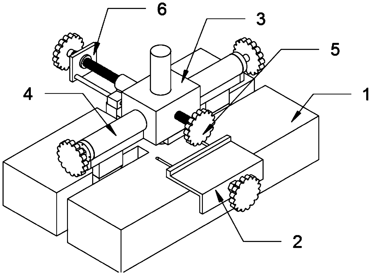
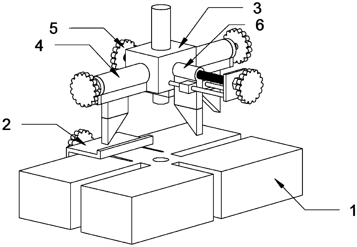
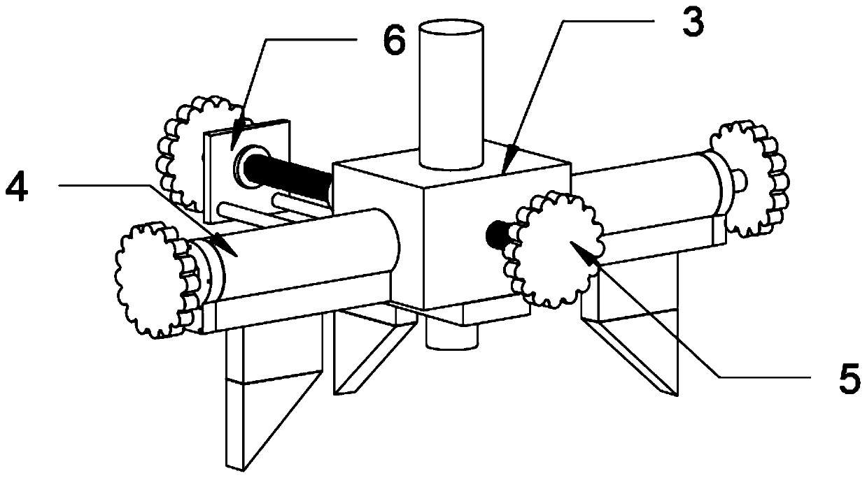
[0036] as attached figure 1 To attach Figure 8 Shown:

[0037]The present invention provides a quick punching device for auto parts, including: a base plate 1, a sliding track 101, a rectangular slot A102, a rectangular slot B103, a limit baffle structure 2, a baffle main body 201, a sliding column 202, and an adjustment stud A203, bearing iron 3, horizontal fixing structure 4, sleeve rod 401, limit cover plate 402, cylindrical iron 403, stud A404, stud B405, horizontal fixing plate 406, first horizontal fixing plate 40601, second horizontal fixing plate 40602, fixing bolt 5, longitudinal fixing structure 6, longitudinal fixing plate 601, first longitudinal fixing plate 60101, second longitudinal fixing plate 60102, cylindrical rod 602, rectangular plate 603, stud C604 and nut 01; bottom plate 1 top surface rear A sliding track 101 is provided at the side position, and a rectangular groove A102 is provided at the middle position of the left end surface and the right end sur...


PUM


Abstract

The invention provides a vehicle part quick punching device. The vehicle part quick punching device comprises a base plate, a stud B and a nut; a slide rail is arranged on the back side of the top endsurface of the base plate; and a longitudinal fixed plate is formed by welding a first longitudinal fixed plate with a second longitudinal fixed plate. Through arrangement of a transverse fixed structure, (1) a stud A and the stud B are opposite in thread direction, so that the stud B is rotated to adjust left-right positions of two transverse fixed plates more quickly and conveniently; (2) second transverse fixed plates on the transverse fixed plates are of right-angled triangular structures, parts can be pushed to a punching station through two second transverse fixed plates during punching; and (3) a thread is arranged on the right end of a limiting cover plate at the right end of the stud B, and is in threaded connection with a nut, so that the stud B can be fixed through the nut after adjustment of the transverse fixed structure to prevent rotation of the stud B in the punching process.

Description

technical field [0001] The invention belongs to the technical field of stamping equipment and machining equipment, and more specifically relates to a quick punching device for auto parts. Background technique [0002] The punching device is a kind of punching device that fixes the parts on the punching plate through the fixture, and then uses the hydraulic device to push the punch to punch the parts. At present, most of the mobile punching machines in China are basically It adopts hydraulic pressure. This kind of hydraulically driven punching machine is favored by the majority of people because of its relatively large output punching force and better punching effect. The punching device is generally composed of a hydraulic expansion device, a punch, a punching plate and a fixed Fixtures, but the current punching device for auto parts is less efficient in punching, and cannot adapt to the current rapid and mass production. [0003] The punching device of existing auto parts ...

Claims


Application Information

Patent Timeline
Patent Type & Authority Patents(China)
IPC IPC(8): B21D28/24B21D37/04
Inventor 陶伟鹏
Owner YANTAI YIHE AUTOMOBILE SCI & TECH CO LTD
Why Eureka
Try Eureka