
System of hot scarfing machine and for positioning head portion of slab and detecting whether steel slab gets stuck or not during scarfing

A flame cleaning and detection system technology, applied in the configuration of indicating equipment/measuring equipment, manufacturing tools, metal processing equipment, etc., can solve problems such as failure to meet high quality requirements, static slab, and burnt surface of slab cleaning, etc. Achieve the effect of novel concept, reduced cutting amount and low scrap rate

Inactive Publication Date: 2019-05-21
SHANGHAI DONGZHEN METALLURGY ENG TECH
View PDF11 Cites 5 Cited by
  • Summary
  • Abstract
  • Description
  • Claims
  • Application Information

AI Technical Summary

Problems solved by technology

[0002] Before cold and hot rolling of high-quality slabs, there are often certain quality requirements for the surface of the slab, but sometimes the high-quality requirements cannot be met in the continuous casting production process, so the slab needs to be cleaned manually or by machine.
In the process of machine flame cleaning of the slab, before the slab cleaning starts, the slab needs to be transported into the cleaning machine so that the distance between the end of the slab and the burner of the cleaning machine is between 50mm and 100mm, and the slab is cleaned with oxygen or The gas heats the molten pool at high temperature within this distance of the slab. After the cleaning is completed, a molten pool pit will appear in the longitudinal direction of the slab. Before the slab enters the cold rolling process, the molten pool pit will be cut off to form a smooth slab. ;During the cleaning process of the slab, the slab conveying roller table moves due to the warping of the slab, the slab is still, and the flame cleaning machine is working, and the flame cleaning machine still uses a large flow of oxygen to clean the slab when the slab is in a static state slab, which will burn off the cleaned surface of the slab

Method used


Image

  • System of hot scarfing machine and for positioning head portion of slab and detecting whether steel slab gets stuck or not during scarfing
  • System of hot scarfing machine and for positioning head portion of slab and detecting whether steel slab gets stuck or not during scarfing

Examples


Embodiment Construction

[0011] Below in conjunction with accompanying drawing and example the present invention is further described

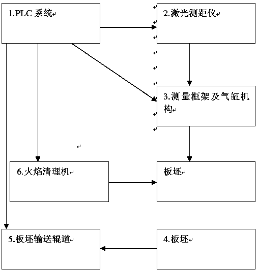
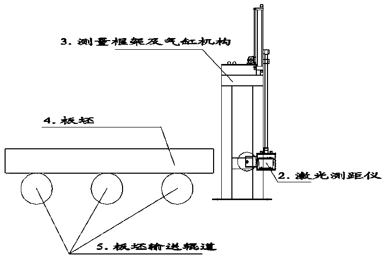
[0012] Real-time example 1: such as figure 1 As shown, it consists of PLC system 1, laser range finder 2, measuring frame and cylinder mechanism 3, slab 4, slab conveying roller table 5 and flame cleaning machine 6, wherein: laser range finder 2 is installed on the measuring frame and On the cylinder mechanism 3, the measuring frame and the cylinder mechanism 3 ride on the slab conveying roller table 5, and the laser range finder 2 directly measures the physical position of the slab 4, and sends it to the PLC system 1 in real time; the slab conveying roller table 5 Drive the slab forward or backward, see the specific schematic diagram figure 2 As shown, the flame cleaning machine 6 adopts a strong oxidation method to clean the surface defects of the moving slab 4, and the PLC system 1 receives the actual physical position of the slab 4 detected by the laser rangefin...


PUM


Abstract

The invention relates to a system of a hot scarfing machine and for positioning the head portion of a slab and detecting whether the steel slab gets stuck or not during scarfing. The system is composed of a PLC system, a laser range finder, a measuring frame and air cylinder mechanism, the slab, a slab conveying roller bed and the hot scarfing machine. The laser range finder is installed on the measuring frame and air cylinder mechanism. The measuring frame and air cylinder mechanism is arranged at one end of the slab conveying roller bed in a riding manner. The slab can move back and forth onthe slab conveying roller bed. The hot scarfing machine is used for cleaning the slab. The PLC system is connected with the laser range finder, the slab conveying roller bed and the hot scarfing machine. The laser range finder is used for directly determining the physical position of the slab, and sends the physical position of the slab to the PLC system in real time. The slab is controlled by the PLC system to carry out position change on the conveying roller bed as a final product, and the PLC system receives the information of the actual physical position detected by the laser range finderin real time so as to control the slab conveying roller bed to move and the hot scarfing machine to clean the final product namely the slab. The system of the hot scarfing machine and for positioningthe head portion of the slab and detecting whether the steel slab gets stuck or not during scarfing is novel in idea, and is stable and reliable in scarfing process.

Description

technical field [0001] The invention relates to a detection system for locating the slab head of a flame cleaning machine and detecting steel stuck during cleaning. Background technique [0002] Before cold and hot rolling of high-quality slabs, there are often certain quality requirements for the surface of the slab, but sometimes the high-quality requirements cannot be met in the continuous casting production process, so the slab needs to be cleaned manually or by machine. In the process of machine flame cleaning of the slab, before the slab cleaning starts, the slab needs to be transported into the cleaning machine so that the distance between the end of the slab and the burner of the cleaning machine is between 50mm and 100mm, and the slab is cleaned with oxygen or The gas heats the molten pool at high temperature within this distance of the slab. After the cleaning is completed, a molten pool pit will appear in the longitudinal direction of the slab. Before the slab ent...

Claims


Application Information

Patent Timeline
Patent Type & Authority Applications(China)
IPC IPC(8): B22D11/16B22D2/00
Inventor 杨帆倪凯敏
Owner SHANGHAI DONGZHEN METALLURGY ENG TECH
Learn More