Supercharge Your Innovation With Domain-Expert AI Agents!

Trolley cam friction driven whole line drive control structure

A technology of friction drive and control structure, applied in the directions of travel mechanism, transportation and packaging, load hanging components, etc., can solve the problems of assembly error of the drive sub-mechanism, difficulty in maintenance, unilateral contact, etc.

Active Publication Date: 2019-05-21
李楠
View PDF5 Cites 0 Cited by
  • Summary
  • Abstract
  • Description
  • Claims
  • Application Information

AI Technical Summary

Problems solved by technology

[0007] Theoretically, there is no positive and negative air travel, but there are multiple driving sub-mechanisms at intervals on the entire line. ①Individual driving sub-mechanisms may have unilateral contact due to assembly errors or deformation during use; ②The upstream friction wheel stops rotating in time and The contact was withdrawn, but the downstream friction wheel did not press and rotate at the same time; ③The upstream friction wheel stopped rotating and exited the contact action t seconds earlier, but the downstream friction wheel was scheduled to press and rotate on time, and there was t seconds of idle travel in the middle
[0008] 2) Positioning accuracy is not easy to achieve
[0009] ①The power connection is not continuous, and there is a gap in the middle, resulting in a positional accuracy that is always poor, far exceeding the allowable value of the error;
[0010] ② There is an error in the brake structure and positioning control, resulting in a positional accuracy that cannot meet the requirements;
[0011] 3) Soft control maintenance is difficult
[0012] One general control device electrically drives multiple drivers, the control circuit is easy to be damaged, and it is difficult to repair if it is broken
Ordinary mechanics in the workshop are not competent, so they can only find the original manufacturer. The maintenance cycle is long, which affects production

Method used


Image

  • Trolley cam friction driven whole line drive control structure
  • Trolley cam friction driven whole line drive control structure
  • Trolley cam friction driven whole line drive control structure

Examples


Embodiment 1

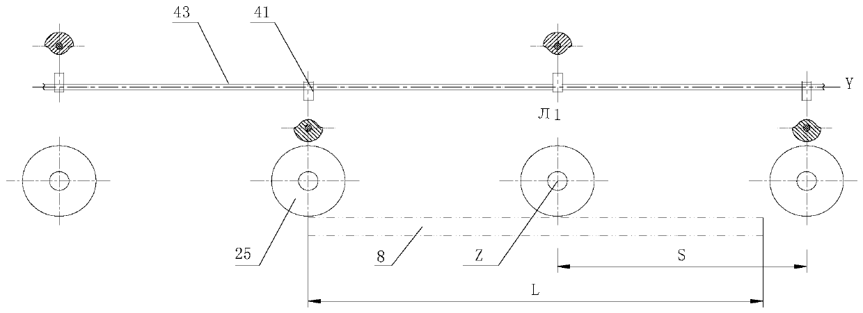
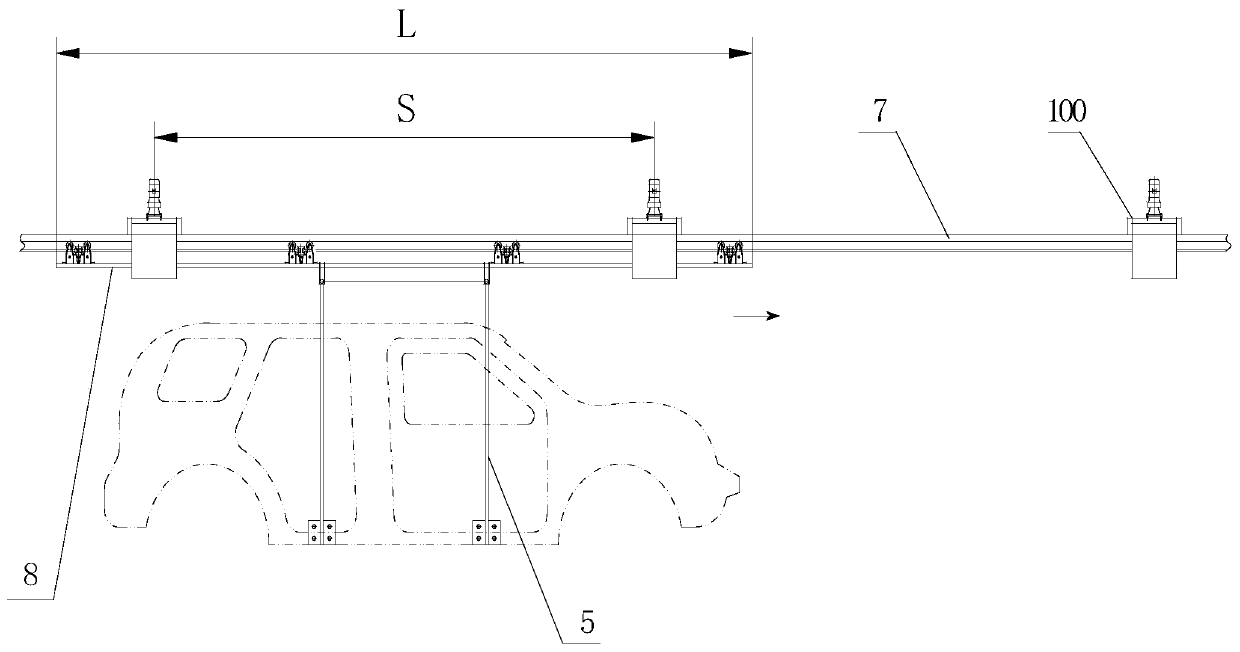
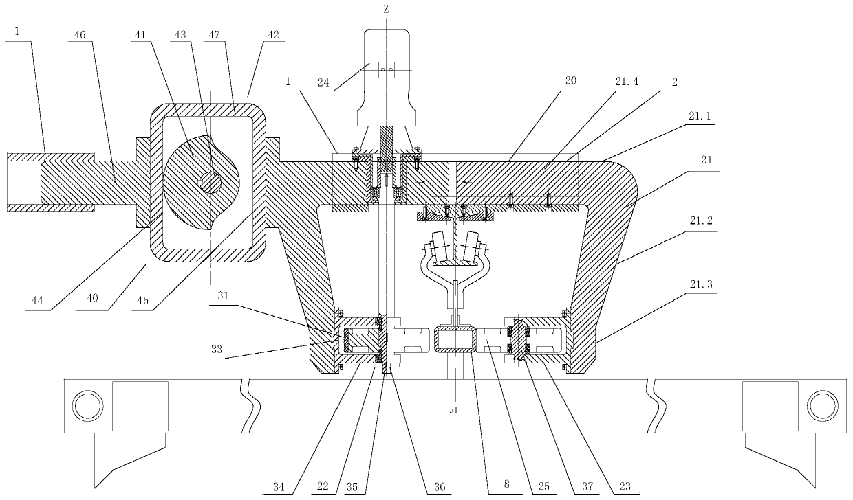
[0046] As shown in the figure, a trolley cam friction driving device 100, the trolley 5 rolls and fits on the lower beam of the I-beam 7 through the guide wheel 6, the trolley 5 includes a driving rod 8, and the driving rod 8 has a plane of symmetry L,

[0047] Including a fixed plate 1, the fixed plate 1 is horizontally fixed on the top of the upper beam of the I-beam 7; the fixed plate is provided with a guide chute 2;

[0048] The guide chute 2 is provided with a friction wheel mechanism 20, and the friction wheel mechanism 20 includes a pair of opening and closing frames 21, and at least one of the opening and closing frames 21 is slidably fitted in the guide chute 2;

[0049] The friction wheel mechanism 20 also includes a driving wheel mechanism 22 and a driven wheel mechanism 23, and the driving wheel mechanism 22 and the driven wheel mechanism 23 are respectively fixed on the opening and closing frame 21; or the friction wheel mechanism 20 also includes a pair of drivi...


PUM


Abstract

The invention discloses a trolley cam friction driven whole line drive control structure. N trolley cam friction driving devices are fixed on an I-shaped beam at intervals; the cam friction driving devices comprise cams and friction wheels; the cams drive the friction wheels to switch between an opened position and a closed position; the structure comprises a long camshaft; the cams and the friction wheels are fixed on the long camshaft at equal intervals in reference to a drive normal plane; the cams comprise matching surfaces; the matching surfaces are alternately arranged about a rotating axis of the long camshaft in an axial symmetry mode; the cams are provided with the same pushing time and return time; and no-idle stroke drive is designed to enable the distance of the nth friction wheel driving a driving rod to advance to be equal to the interval distance at the pushing time of the nth cam. The whole line no-idle stroke drive control structure realizes no-idle stroke friction driving from the structural design angle, achieves precise control, and reduces the maintenance cost.

Description

technical field [0001] The invention relates to the technical field of friction conveying systems, in particular to a whole-line driving control structure for cam friction driving of trolleys. Background technique [0002] The friction wheel drive of the crane is a mechanical transmission that uses the friction force generated by the direct contact and compression of the friction wheel to achieve power transmission. The friction force generated by the pressing force between the driving wheel and the driven wheel drives the driving rod to move in a straight line, which actually continuously expands the rotational motion of the driving wheel into the linear motion of the driven rod. [0003] A complete set of friction conveying equipment is composed of several drive stations. The friction wheel is rotated by the driving motor. The friction wheel and the auxiliary wheel clamp the beam of the conveying trolley in the middle through the spring. The side of the friction wheel is ...

Claims


Application Information

Patent Timeline
Patent Type & Authority Applications(China)
IPC IPC(8): B66C9/14
Inventor 李楠
Owner 李楠
Features
  • R&D
  • Intellectual Property
  • Life Sciences
  • Materials
  • Tech Scout
  • Unparalleled Data Quality
  • Higher Quality Content
  • 60% Fewer Hallucinations
Learn More