
Permeable spur dike structure

A technology of spur dikes and permeable holes, which is applied in water conservancy projects, sea area engineering, coastline protection, etc., can solve problems such as insufficient flood discharge capacity of large flows, lack of ecological functions of permeable spur dikes, and insufficient water blocking of small flows, so as to improve the ecological environment of rivers Effect

Active Publication Date: 2019-05-21
TIANJIN RES INST FOR WATER TRANSPORT ENG M O T
View PDF8 Cites 7 Cited by
  • Summary
  • Abstract
  • Description
  • Claims
  • Application Information

AI Technical Summary

Problems solved by technology

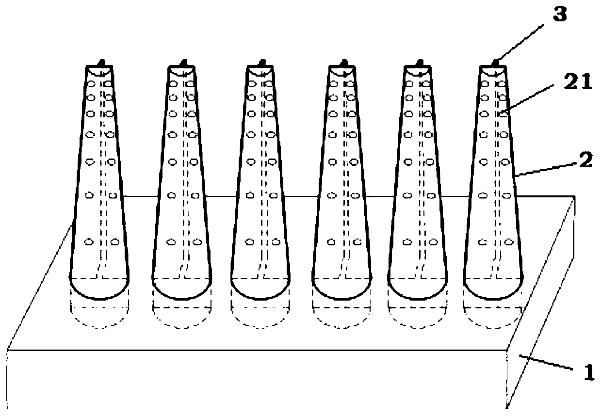
[0003] In the practice of inland waterway treatment, the existing permeable spur dikes have played a very good role in reducing the flow velocity around the dam body, promoting side bank siltation, narrowing the wide river channel, and improving the navigable water depth, but there are still some problems: ①Pile type, lattice Floating objects on the facing surface of permeable spur dikes are easy to stick and accumulate, resulting in permeable spur dikes becoming semi-permeable or even impermeable spur dikes, affecting the function of flood discharge during flood seasons, and sticking floating debris after receding water is likely to cause ecological problems; ② Existing The permeable spur dikes have constant water permeability at different flows, and the water resistance is not enough for small flows, and the flood discharge capacity for large flows is insufficient; ③Recent waterway management has more and more ecological demands on buildings, and the ecological functions of permeable spur dikes are relatively lacking at present

Method used


Image

  • Permeable spur dike structure
  • Permeable spur dike structure
  • Permeable spur dike structure

Examples


Embodiment Construction

[0031] The following will clearly and completely describe the technical solutions in the embodiments of the present invention with reference to the accompanying drawings in the embodiments of the present invention. Obviously, the described embodiments are only some, not all, embodiments of the present invention. Based on the embodiments of the present invention, all other embodiments obtained by persons of ordinary skill in the art without making creative efforts belong to the protection scope of the present invention.

[0032] The purpose of the present invention is to provide a permeable spur dam structure to solve the problems existing in the prior art, so that the permeable spur dam can prevent the adhesion and accumulation of floating objects on the water surface, adapt to the water permeability requirements of different river flows, and improve the ecological environment of the river.

[0033] The invention provides a permeable spur dam structure, which includes a plurali...


PUM

PropertyMeasurementUnit
Depthaaaaaaaaaa
Diameteraaaaaaaaaa
Lengthaaaaaaaaaa

Abstract

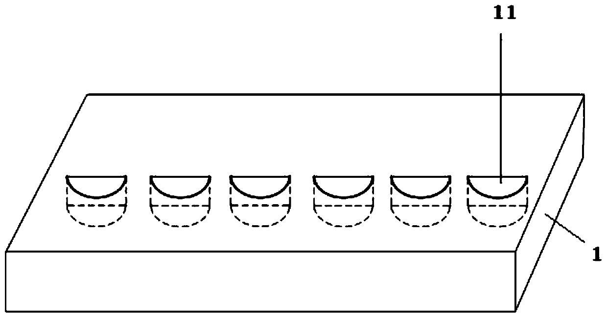
The invention discloses a permeable spur dike structure, and belongs to the field of river channel treatment. The permeable spur dike structure comprises a plurality of structure units connected sideby side; each structure unit comprises a concrete base and a plurality of concrete piles; the plurality of concrete piles are uniformly distributed on the same straight line on the concrete base at intervals; the sectional area of the concrete pile is gradually reduced from bottom to top; the bottom of the concrete pile is fixedly connected with the concrete base; the upstream face of the concretepile is an arc-shaped face; a plurality of water permeable holes are formed in the concrete pile; and the distribution density of the water permeable holes is gradually increased from bottom to top.According to the invention, river floaters are effectively prevented from adhering and accumulating on the pile body; the higher the elevation of the spur dike is, the higher the water permeability is, so that the spur dike can automatically adjust the water blocking and flood discharging capacities when the river flow changes; a slow flow area formed by the concrete piles and the concrete base can be used for water grass growth and can also be used for providing places needed for fish to inhabit, bait, breed and develop; and therefore the ecological environment of a river can be effectively improved through the ecological characteristics of the structure.

Description

technical field [0001] The invention relates to the field of river channel management, in particular to a permeable spur structure. Background technique [0002] Spur dam is a waterway improvement structure that extends into the river channel orthogonally or obliquely to the river bank. It is widely used in waterway improvement projects in river sections with wide rivers, shallow water and slow flow. The main functions are to gather water to attack sand and prevent erosion Promote siltation and increase water depth of channel. A dam body that is permeable is called a permeable spur dam, and a dam body that is impervious to water is called an impermeable spur dam. The impermeable spur dike has a strong effect on controlling water flow, while the permeable spur dike has a slightly weaker effect on controlling water flow and scouring the navigation channel, but has a better effect on promoting siltation and has a weaker impact on dikes and ecology. In large alluvial rivers su...

Claims


Application Information

Patent Timeline
IPC IPC(8): E02B3/06E02B8/06
Inventor 朱玉德刘晓菲刘鹏飞张明进刘万利杨宗默李少希
Owner TIANJIN RES INST FOR WATER TRANSPORT ENG M O T
Learn More