Construction device for building waterproof layer

A construction device and building waterproofing technology, applied in construction, protection device, building structure and other directions, can solve the problems of low construction efficiency, high labor cost, poor straightness of coiled material, etc., and achieve good cohesion, fast waterproof material, The effect of improving the waterproof effect

Active Publication Date: 2019-05-21
烟台蒙特防水材料有限公司
View PDF7 Cites 5 Cited by
  • Summary
  • Abstract
  • Description
  • Claims
  • Application Information

AI Technical Summary

Problems solved by technology

[0003] In order to make up for the deficiencies in the prior art, a building waterproof layer construction device proposed by the present invention can solve the problem of low construction efficiency and high labor cost o

Method used


Image

  • Construction device for building waterproof layer
  • Construction device for building waterproof layer
  • Construction device for building waterproof layer

Examples


Example Embodiment

[0024] Example 1

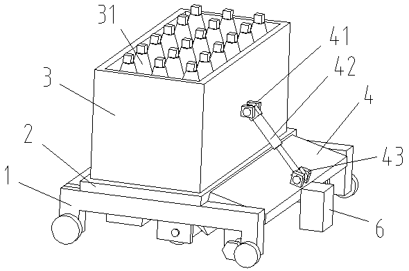
[0025] Such as Figure 1 to Figure 3 As shown, the construction device for building waterproof layer according to the present invention is characterized in that it comprises a trolley 1. The trolley 1 adopts a flat car in the prior art, and the upper side of the trolley 1 is fixedly connected to a supporting seat plate 2, and the supporting seat plate 2 The side is fixedly connected to the gas source box 3, the gas source box 3 is equipped with oxygen and acetylene gas cylinders 31, and one side of the supporting seat plate 2 is connected to the base plate 4 through a hinge. One side of the air source box 3 is hingedly fixed to one end of the electric push-pull rod 42 through the first hinge base 41, and the other end of the electric push-pull rod 42 is hinged and fixed to the base plate 4 through the second hinge base 43, and the base plate 4 is controlled to be supported along by the electric push-pull rod 42 The seat plate 2 rotates on one side.

[0026] A d...

Example Embodiment

[0031] Example 2

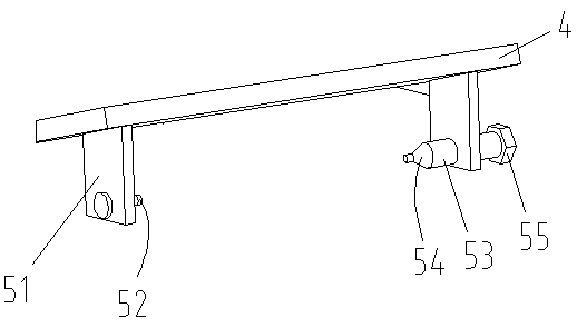
[0032] The heating device in Embodiment 1 can be replaced by the following structure: the heating device includes two mounting plates 61 arranged in parallel, the two mounting plates 61 are welded and fixed to the base plate 4, and the guide rod 62 is fixedly connected between the two mounting plates 61 , The screw rod 63 is rotated and matched between the two mounting plates 61. One end of the screw rod 63 penetrates the mounting plate 61 and extends to the outside of the mounting plate 61. The mounting plate 61 is equipped with a motor 64 for driving the screw 63 to rotate. The main shaft of 64 is coaxial and fixedly connected with the screw 63.

[0033] The heating device also includes a slider 71. One side of the slider 71 is provided with a sliding hole 711 and a screw threaded hole 712. The guide rod 62 passes through the sliding hole 711, and the screw 63 is in the screw threaded hole 712. Through the threaded connection, the slider 71 can slide back and ...


PUM


Abstract

The invention relates to building waterproof construction, and in particular relates to a construction device for a building waterproof layer. The device comprises a trolley, the upper side of the trolley is fixedly connected with a supporting base plate, the upper side of the supporting base plate is fixedly connected with an air source box, an air bottle is arranged in the air source box, one side of the supporting base plate is rotationally connected with a base plate, one end of an electric push-pull rod is hinged and fixed to one side of the air source box, the other end of the electric push-pull rod is hinged and fixed to the base plate, and the electric push-pull rod controls the base plate to rotate along one side of the supporting base plate. According to the invention, a waterproof coiled material is laid through the walking of the trolley. The connection between the laid waterproof coiled materials is good, the waterproof effect of the waterproof coiled material is effectively improved. The device can rapidly replace the waterproof coiled material, the waterproof coiled material can be secondarily heated and rolled after laying is completed, the waterproof coiled material can be well adhered to the surface of a building, and the number of constructors can be reduced while the construction efficiency is improved.

Description

technical field [0001] The invention relates to the technical field of building waterproof construction, in particular to a building waterproof layer construction device. Background technique [0002] Waterproof membrane is mainly used in building walls, roofs, and sewage treatment, etc., to resist external rainwater and groundwater leakage, a flexible building material product that can be rolled into rolls, and used as a link between the engineering foundation and the building The leak-free connection is the first barrier for the waterproofing of the entire project and plays a vital role in the entire project. In engineering construction, waterproofing is an important item, and its quality directly determines the quality of the project. When doing waterproofing, the traditional method is to spray concrete on the surface of the building, and then lay waterproof materials, waterproof materials such as Figure 10 As shown, a round tube 100 is included, and the outer side of t...

Claims


Application Information

Patent Timeline
IPC IPC(8): E04D15/06E04G21/16E02D31/02
Inventor 徐善龙许光辉石小利王志刚
Owner 烟台蒙特防水材料有限公司
Why Eureka
Try Eureka