
Numerical simulation method for multi-field coupling induced electromotive force of electromagnetic flow sensor

A technology for inducting electromotive force and electromagnetic flow, which is applied in the field of flow sensors, can solve problems such as inability to calculate with non-circular indented electromagnetic flow sensors, and achieve accurate simulation results

Active Publication Date: 2019-05-21
HEFEI UNIV OF TECH
View PDF6 Cites 12 Cited by
  • Summary
  • Abstract
  • Description
  • Claims
  • Application Information

AI Technical Summary

Problems solved by technology

But at present, there is only the theoretical formula of the weight function of the circular tube point electrode, so this method is only suitable for the calculation of the induced electromotive force of the circular tube point electrode electromagnetic flow sensor, and cannot be used for the calculation of the non-circular indented electromagnetic flow sensor
At the same time, the method replaces the induced electromotive force of the actual structural size with the result of the two-dimensional induced electromotive force, and ignores the actual structural size of the electrode, which is different from the actual working condition of the sensor. Therefore, the calculation method of the induced electromotive force has great limitations. sex

Method used


Image

  • Numerical simulation method for multi-field coupling induced electromotive force of electromagnetic flow sensor
  • Numerical simulation method for multi-field coupling induced electromotive force of electromagnetic flow sensor
  • Numerical simulation method for multi-field coupling induced electromotive force of electromagnetic flow sensor

Examples


Embodiment Construction

[0053] The present invention will be further described below in conjunction with the accompanying drawings.

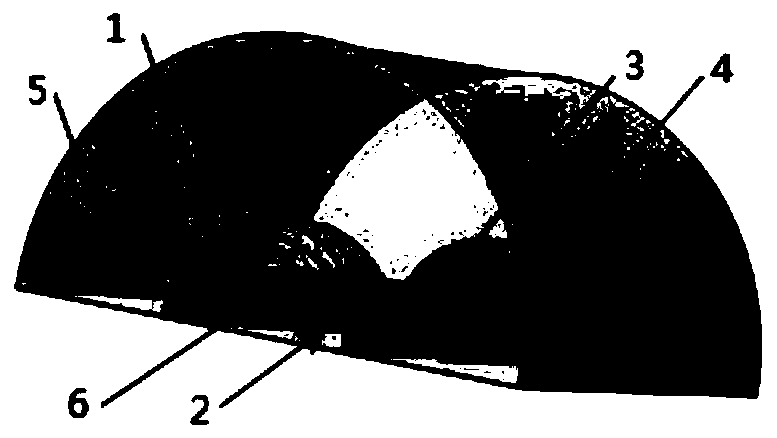
[0054] The present invention uses rectangular indentation electromagnetic flow sensor, such as figure 1 As shown as an example, the method and process of multi-field coupling induced electromotive force are explained through the numerical analysis software COMSOL, figure 2 It is a flowchart of the present invention, and the concrete steps are as follows:

[0055] (1) Prepare, open the COMSOL software, and select the spatial dimension in the model wizard;

[0056] (2) Determine the spatial dimension;

[0057] In order to truly reflect the various physical quantities of the electromagnetic flow sensor, a three-dimensional space dimension is selected.

[0058] (3) Add physics field;

[0059] According to the working principle of the electromagnetic flow sensor, the present invention needs to add four physical field interfaces, choose to add turbulent flow, k-ε model ...


PUM

PropertyMeasurementUnit
Conductivityaaaaaaaaaa

Abstract

The invention relates to a numerical simulation method for the multi-field coupling induced electromotive force of an electromagnetic flow sensor. The method comprises the steps of determining a three-dimensional space dimension; adding a physical field interface according to the action mechanism of the electromagnetic flow sensor; constructing a geometric model; defining the material attribute ofeach part of the sensor; modifying the setting of each physical field, and defining boundary conditions; performing grid division; adding research types and carrying out calculation and solution; andfinally, carrying out post-processing on a calculation result to obtain a required physical quantity, especially a coupling induced electromotive force. The flow field and magnetic field distributionin the sensor can be obtained through simulation according to the actual structural size of the electromagnetic flow sensor, and the induced electromotive force is obtained by directly coupling the flow field and the magnetic field simulation result; no idealized assumption is needed, compared with induced electromotive force obtained through calculation based on a weight function formula and other methods, the induced electromotive force better conforms to the actual situation, the simulation result of the electromagnetic flow sensor is more accurate, and related research on structural optimization design of the sensor is facilitated.

Description

technical field [0001] The invention relates to the technical field of flow sensors, in particular to a numerical simulation method for multi-field coupling induced electromotive force of an electromagnetic flow sensor. Background technique [0002] The electromagnetic flow sensor is a detection instrument for measuring the volume flow of conductive liquid according to Faraday's law of electromagnetic induction. When passing through the measuring pipe, the magnetic force line will be cut to generate an electric potential, and the electric potential difference is obtained through the electrodes to obtain the induced electromotive force; when the sensor’s measuring pipe and the magnetic circuit structure parameters are different, the flow field and magnetic field distribution characteristics in the sensor will change, so the flow The induced electromotive force generated by the coupling of the field and the magnetic field will change accordingly, which will directly affect the...

Claims


Application Information

Patent Timeline
IPC IPC(8): G01F25/00G06F17/50
Inventor 梁利平葛玉石徐科军黄云志杨双龙许伟吴建平齐飞燕
Owner HEFEI UNIV OF TECH
Learn More