Method for testing optimal spring stiffness coefficient of elastic hydrofoil of wave glider

A test method and stiffness coefficient technology, which is applied in the field of shipbuilding and ocean engineering, can solve the problems of inaccurate positioning, large changes in the motion speed of wave glider, and the inability of trailer equipment to provide the heave force and motion effect of the mother ship on the underwater glider. Achieve the effects of avoiding motion interference, easy positioning, and high accuracy

Active Publication Date: 2019-05-21
SHANGHAI JIAO TONG UNIV
View PDF7 Cites 3 Cited by
  • Summary
  • Abstract
  • Description
  • Claims
  • Application Information

AI Technical Summary

Problems solved by technology

Because the wave glider is composed of two parts, the underwater tractor and the surface mother ship, the trailer equipment cannot provide the heave force and movement effect of the mother ship on the underwater glider during the hydrodynamic performance test of the underwater tractor, and cannot simulate the relationship between the surface mother ship and the water surfa

Method used


Image

  • Method for testing optimal spring stiffness coefficient of elastic hydrofoil of wave glider
  • Method for testing optimal spring stiffness coefficient of elastic hydrofoil of wave glider
  • Method for testing optimal spring stiffness coefficient of elastic hydrofoil of wave glider

Examples


Embodiment 1

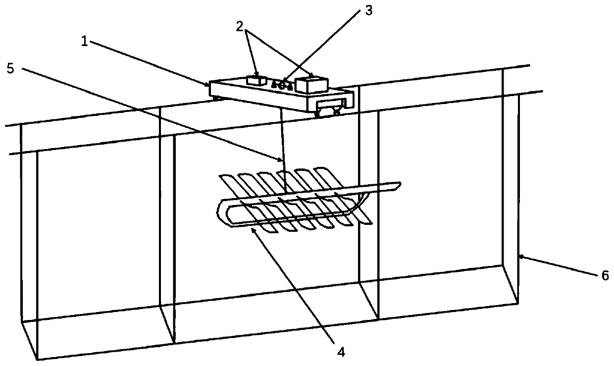
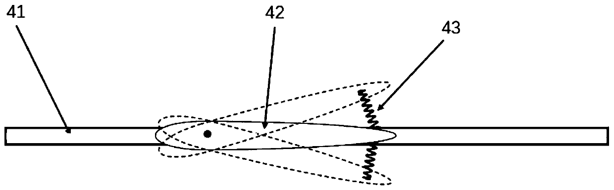
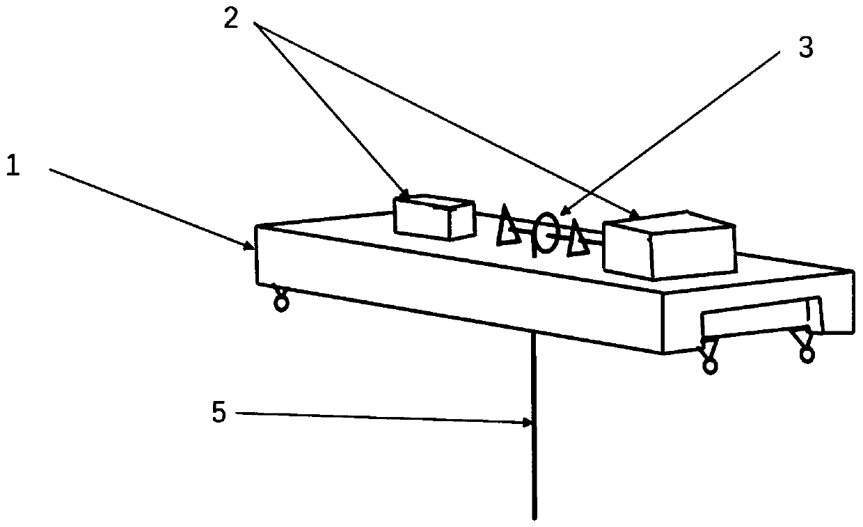
[0039] Such as figure 1 As shown, the test device required in this test method includes a vertical excitation trolley, an underwater tractor model 4, a traction line 5 and a water tank 6; the vertical excitation trolley includes a trailer carrier 1, a heave excitation control device 2 and a sheave 3; Such as figure 2 As shown, the underwater tractor model 4 used in this test method includes a body 41 , an elastic hydrofoil 42 and a spring 43 .

[0040] When conducting the test, first configure the test device used for the test:

[0041] 1. Fix and wind the upper end of the traction line 5 on the sheave 3;

[0042] 2. Fix the lower end of the traction line 5 at the physical center of gravity of the underwater tractor model 4;

[0043] 3. Install the vertical excitation trolley on the guide groove of the water tank 6;

[0044] 4. Place the underwater tractor model 4 in the water tank 6 and completely submerge it in the water.

[0045] In the above configuration process, th...

Embodiment 2

[0048]Install the spring 43 studied in this test method between the body 41 and the elastic hydrofoil 42, and ensure that after the spring 43 is installed, the elastic hydrofoil 42 remains horizontal under the action of the spring 43 while the body 41 remains horizontal in the water. After the installation is completed, use the similarity law to calculate the amplitude of the underwater traction machine model 4 corresponding to the real sea state wave height in the test, and obtain the corresponding power shaft rotation angle by the calculation method of the above amplitude, and control the heave excitation control device 2 through the excitation control set to produce an amplitude that meets the test requirements. At the same time, it should be noted that the amplitude of the underwater tractor model 4 must be less than the depth of the underwater tractor model 4 being immersed in water, so as to ensure that the heave excitation control device 2 can control the underwater tract...

Embodiment 3

[0050] When the heave excitation control device 2 applies heave excitation to the underwater tractor model 4, the vertical excitation trolley will move forward, because the edge surface of the water tank 6 for the sliding of the vertical excitation trolley is not completely flat, and the length of one grid of the water tank 6 is only 1.5 meters, so the time required for the car to pass through the three grids is measured, and its average speed is calculated to characterize the performance of the elastic hydrofoil of the wave glider. At this time, record the average time required for the vertically excited car to pass through the 3-grid water tank, and calculate the movement speed of the vertically excited car under the specific stiffness coefficient of the spring 43 and the specific amplitude of the underwater tractor model 4, so as to characterize The sporty performance of a wave glider. Using the control variable method, replace the spring 43 with different stiffness coeffic...


PUM

PropertyMeasurementUnit
Elastic coefficientaaaaaaaaaa

Abstract

The invention discloses a method for testing the optimal spring stiffness coefficient of an elastic hydrofoil of a wave glider. A vertical excitation trolley, an underwater tractor model of a wave glider, a pull wire and a water tank form a test device, the vertical excitation trolley is used for replacing a wave glider water surface mother ship to apply heaving excitation to the underwater tractor model, thus he influence of water surface waves on the underwater tractor caused by the size limitation of the test device is eliminated, and the optimal spring stiffness coefficient of the wave glider in a specified working environment is researched by comparing the average movement speed of the vertical excitation trolley and applying a control variable method. The method is simple and easy toimplement, capable of carrying out simulation experiments on the wave glider more accurately and truly, high in accuracy and convenient to position.

Description

technical field [0001] The invention relates to the field of ships and marine engineering, in particular to a test method for the optimal spring stiffness coefficient of an elastic hydrofoil of a wave glider. Background technique [0002] At present, the hydrodynamic performance tests of ships and ocean engineering structures mainly rely on pools and tanks. The current test equipment for pools and tanks can meet the hydrodynamic test requirements of traditional ships and ocean engineering structures. Aircraft, such as wave gliders, were not able to meet its test requirements. [0003] The sailing speed of the wave glider is mainly determined by the motion performance of the underwater part. The underwater performance of the wave glider is not only related to the forbidden angle, but also related to the stiffness coefficient of the spring on the elastic hydrofoil, and is also affected by the actual sea conditions. Because the wave glider is composed of two parts, the underw...

Claims


Application Information

Patent Timeline
IPC IPC(8): G01M10/00
Inventor 田新亮周润婕王鹏李家炜张芳园李欣寇雨丰刘浩学
Owner SHANGHAI JIAO TONG UNIV
Why Eureka
Try Eureka