Underwater vehicle positioning method based on baseline geometric structure constraint

An underwater vehicle and geometric structure technology, which is applied to instruments, re-radiation of sound waves, radio wave measurement systems, etc., can solve the problems of positioning failure, affecting the efficiency of task execution, delay and packet loss of underwater acoustic positioning information, etc. To achieve the effect of improving positioning accuracy

Active Publication Date: 2019-05-21
NO 20 RES INST OF CHINA ELECTRONICS TECH GRP
View PDF6 Cites 6 Cited by
  • Summary
  • Abstract
  • Description
  • Claims
  • Application Information

AI Technical Summary

Problems solved by technology

[0003] In the current underwater vehicle positioning process, if only the inertial / dead reckoning positioning method is used, limited by the size and load capacity of the underwater vehicle, the positioning accuracy of the inertial sensors it can carry is limited, and underwater navigation is required. The GPS, Beidou and other systems are used for position correction, which affects the efficiency of task execution; and if only underwater acoustic beacons are used for positioning, it is prone to delays and delays in underwater acoustic positioning information due to the influence of the complex underwater environment. Phenomena such as packet loss, causing positioning failure at some times
In addition, the relatively accurate position and distance information between multiple acoustic beacons has not been fully utilized, and the geometric structure relationship between the baselines of the acoustic beacons has not been paid enough attention to the constraint effect on the distance measurement error.

Method used


Image

  • Underwater vehicle positioning method based on baseline geometric structure constraint
  • Underwater vehicle positioning method based on baseline geometric structure constraint
  • Underwater vehicle positioning method based on baseline geometric structure constraint

Examples


Embodiment Construction

[0035] The present invention will be further described below in conjunction with the accompanying drawings and embodiments, and the present invention includes but not limited to the following embodiments.

[0036] Technical scheme of the present invention comprises the following steps:

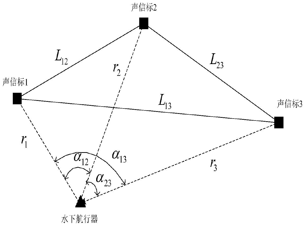
[0037] Step 1: Three underwater acoustic beacons with self-location function broadcast their positions at fixed time intervals (x i ,y i )(i=1, 2, 3), the underwater vehicle uses the received underwater acoustic signal to delay the time Δt i and regional underwater mean speed of sound to calculate the 3D measurement distance between each beacon Use the carried depth gauge to accurately measure the depth value h of the underwater vehicle, and measure the 3D distance l i Convert to Plane 2D Measure Distance

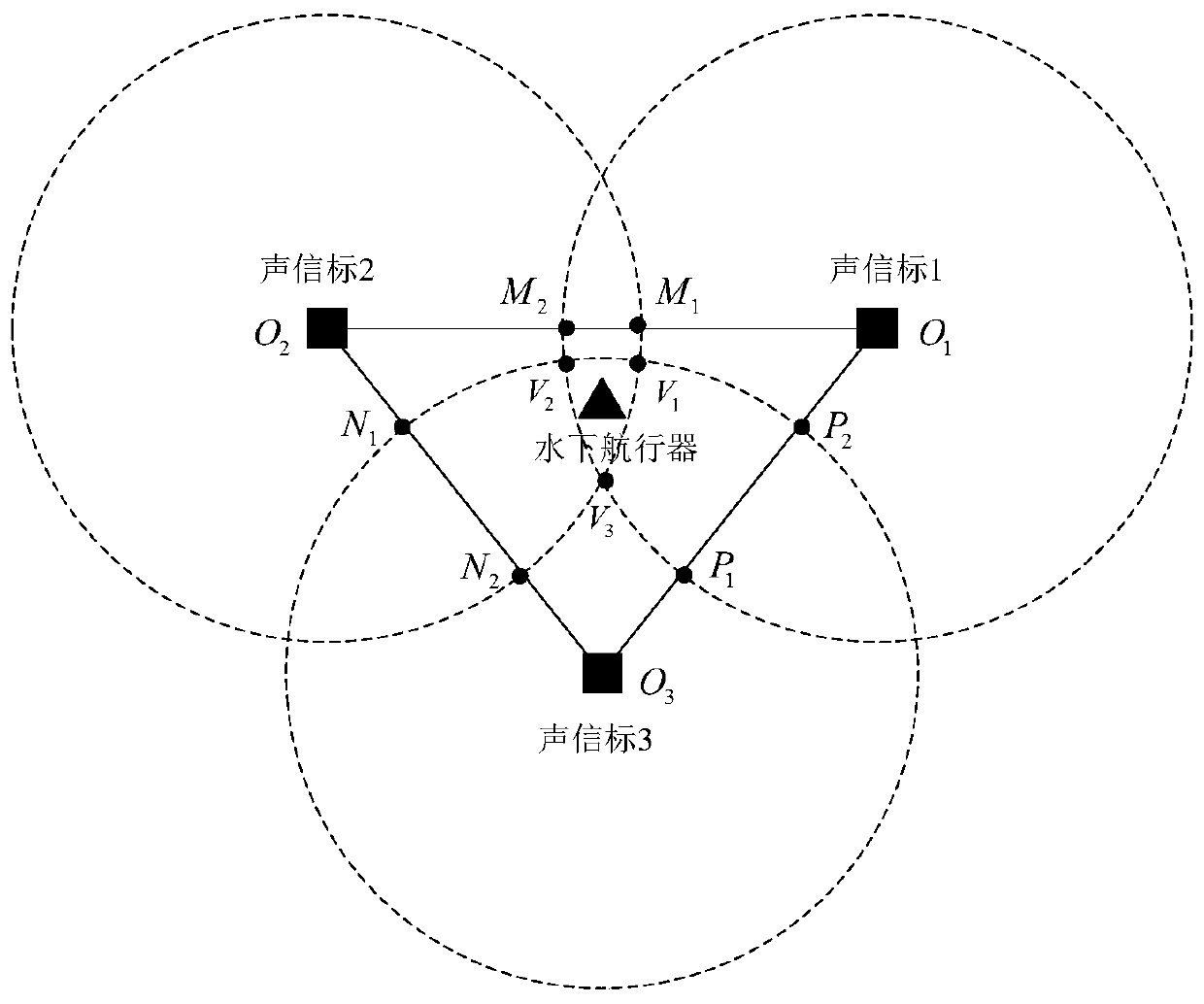
[0038] Step 2: Calculate the distance L between two beacons (that is, the positioning baseline) based on the known beacon positions ij (i, j=1, 2, 3 and i≠j), use the geometric st...


PUM


Abstract

The invention provides an underwater vehicle positioning method based on baseline geometric structure constraint, comprising the steps of calculating to obtain a 3D measurement distance between everytwo beacons; calculating the distance between every two beacons, and constructing an equality constraint condition and an inequality constraint condition of a 2D calculated distance between each beacon and the current position of an underwater vehicle; and obtaining predicted positioning information, establishing a relative distance measurement equation between the water surface beacon and the underwater vehicle, and obtaining the position, the course and the pitch estimation value of the underwater vehicle by solving a constraint optimization problem. According to the method, an underwater inertia / dead reckoning positioning method and an underwater acoustic positioning method are combined, and long-time effective and accurate positioning of the underwater vehicle is ensured; the distanceinformation between the acoustic beacons is effectively utilized in the positioning process; and by means of the maximum posteriori estimation criterion and extended Kalman filtering, constraint conditions are effectively fused into the positioning solving process, and the positioning precision of the underwater vehicle is improved.

Description

technical field [0001] The invention belongs to the field of underwater acoustic navigation and positioning, specifically relates to a positioning method for an underwater vehicle, and is also applicable to the positioning process of other various underwater autonomous moving targets. Background technique [0002] Because radio signals are easily absorbed and attenuated rapidly when they propagate underwater, it is difficult for GPS, Beidou and other systems commonly used for land and air target navigation to be directly used for accurate positioning of underwater vehicles. At present, the positioning technology of underwater vehicles can be mainly divided into three categories: (1) inertial / dead reckoning positioning; (2) geophysical positioning; (3) underwater acoustic positioning. The advantage of inertial / dead reckoning positioning technology is that it can perform all-weather and all-region autonomous positioning without relying on external information sources. However,...

Claims


Application Information

Patent Timeline
Patent Type & Authority Applications(China)
IPC IPC(8): G01S15/46G01S7/52
Inventor 马朋胡安平康建荣王伟
Owner NO 20 RES INST OF CHINA ELECTRONICS TECH GRP
Why Eureka
Try Eureka