Detecting method and monitoring system for coupling fault of rotating machine

A technology for coupling faults and rotating machinery, applied in general control systems, control/regulation systems, instruments, etc., can solve problems such as poor fault detection accuracy, and achieve the effect of being convenient for practical application

Inactive Publication Date: 2019-05-21
CHINA UNIV OF PETROLEUM (EAST CHINA) +1
View PDF14 Cites 22 Cited by
  • Summary
  • Abstract
  • Description
  • Claims
  • Application Information

AI Technical Summary

Problems solved by technology

[0005] Aiming at the problem of poor fault detection accuracy when existing fault detection methods detect coupling faults, the presen

Method used


Image

  • Detecting method and monitoring system for coupling fault of rotating machine
  • Detecting method and monitoring system for coupling fault of rotating machine
  • Detecting method and monitoring system for coupling fault of rotating machine

Examples


Embodiment 1

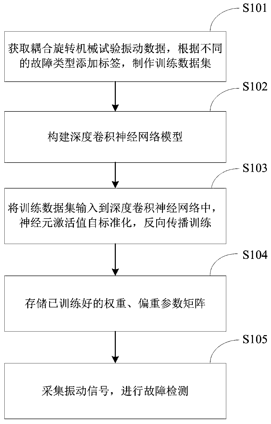
[0121] Embodiment 1: A comprehensive test bench for fault diagnosis of wind turbine power transmission is adopted, and vibration signals of coupling faults of bearings and gears of parallel-axis gearboxes are collected through acceleration sensors on the test bench. Vibration signal, make training data set and test data set.

[0122] There are 12 different fault types in the collected vibration signals, see Table 2. It can be seen from Table 2 that the 12 types of faults are: (1) normal condition N, (2) inner ring bearing fault IF, (3) roller bearing fault condition RF, (4) outer ring bearing fault OF, (5) Coupling failure IRO for inner ring, ball and outer ring condition, (6) coupling failure for ball bearing and notched gear condition (RCH), (7) coupling failure for ball bearing and cracked gear condition (RCR), (8) outer ring Coupling failure occurs in bearing and tooth-missing gear state (OCH), coupling fault occurs in (9) outer ring bearing and cracked gear state (OCR), ...

Embodiment 2

[0131] Embodiment 2: In order to verify that the rotating machinery coupling fault monitoring system of the present invention can meet the real-time requirements of online monitoring, the relationship between the time and the batch size when testing the diagnostic data of the monitoring system is tested. By testing on different batch sizes, it can be obtained that the time required for the proposed system to diagnose a signal is about 44ms, and the sampling frequency of the acceleration sensor that collects mechanical vibration signals in the wind turbine power transmission fault diagnosis comprehensive test bench is 5.12KMz , each sample signal takes 2048 sampling points, and the relationship between time and batch size is shown in Table 5. It can be seen from Table 5 that the rotating machinery coupling fault monitoring system of the present invention can well meet the real-time requirements.

[0132] table 5

[0133] batch size


PUM


Abstract

The invention relates to a detecting method and a monitoring system for a coupling fault of a rotating machine. The detecting method comprises the steps of using vibrating signal data which are acquired by the rotating machine in a normal working condition and a fault working condition as a training data set, establishing a deep convolutional neural network model, directly using the vibration dataas an input, introducing a self-normalizing strategy for standardizing a neuron activating value, training the parameter of the deep convolutional neural network model, storing the trained parameterdata, acquiring the data in a real-time working condition as testing data, and realizing fault detection through the deep convolutional neural network model. The detecting method and the monitoring system have advantages of realizing no requirement for an accurate mathematical model of an industrial process, facilitating actual application, realizing fault detection and fault working condition classification, effectively monitoring a specific component with mechanical damage, and realizing high detection accuracy.

Description

technical field [0001] The invention belongs to the technical field of industrial machinery monitoring and fault diagnosis, and relates to a detection method and a monitoring system for coupling faults of rotating machinery. Background technique [0002] In modern industrial production, fault diagnosis of complex electromechanical systems by collecting vibration signals of mechanical components is one of the most widely used diagnostic methods in fault diagnosis of rotating machinery. Traditional vibration diagnosis methods and theories have matured, and its core is usually divided into two parts: one is the feature extraction of vibration signals, and the other is pattern classification. [0003] Rotating machinery refers to the machinery that mainly relies on rotating actions to complete specific functions. It is widely used in mechanical equipment. Among them, gears and shafts are key components with high application rates. Their state and geometric characteristics play a...

Claims


Application Information

Patent Timeline
IPC IPC(8): G05B13/04
Inventor 盛立牟大伟高明周东华
Owner CHINA UNIV OF PETROLEUM (EAST CHINA)
Why Eureka
Try Eureka