
A satellite optical communication terminal in-orbit calibration and transceiving coaxiality correction device and method

A technology of satellite optical communication and correction device, which is applied in satellite communication transmission, electromagnetic wave transmission system, electrical components and other directions, can solve the problem of inability to correct the coaxiality of transceivers, etc. Cost, the effect of correcting the coaxiality of the transceiver

Inactive Publication Date: 2019-05-21
XI'AN INST OF OPTICS & FINE MECHANICS - CHINESE ACAD OF SCI +1
View PDF3 Cites 20 Cited by
  • Summary
  • Abstract
  • Description
  • Claims
  • Application Information

AI Technical Summary

Problems solved by technology

[0008] The purpose of the present invention is to overcome the defects in the prior art that only the optical axis position of the receiving and receiving optical axis can be calibrated, but the coaxiality of the transmitting and receiving is unable to be corrected, and to provide a device and method for on-orbit calibration of satellite optical communication terminals and correction of the coaxiality of transmitting and receiving. Check the tracking and communication status of satellite optical communication terminals to meet the requirements of satellite laser communication terminals for on-orbit self-calibration

Method used


Image

  • A satellite optical communication terminal in-orbit calibration and transceiving coaxiality correction device and method
  • A satellite optical communication terminal in-orbit calibration and transceiving coaxiality correction device and method
  • A satellite optical communication terminal in-orbit calibration and transceiving coaxiality correction device and method

Examples


Embodiment Construction

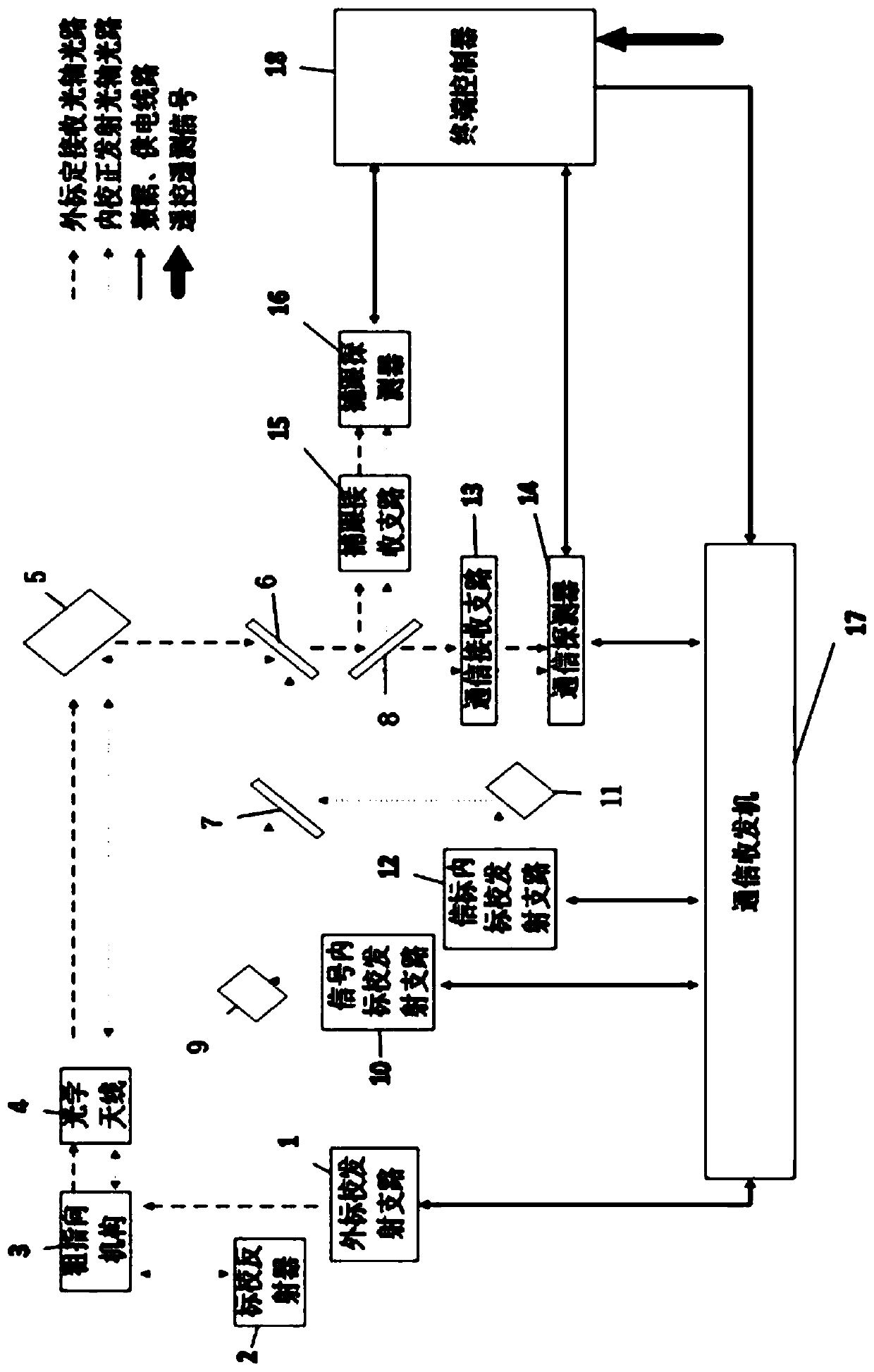
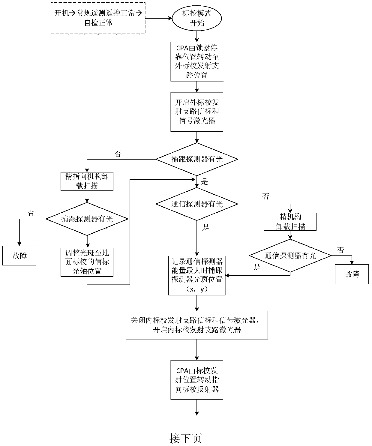
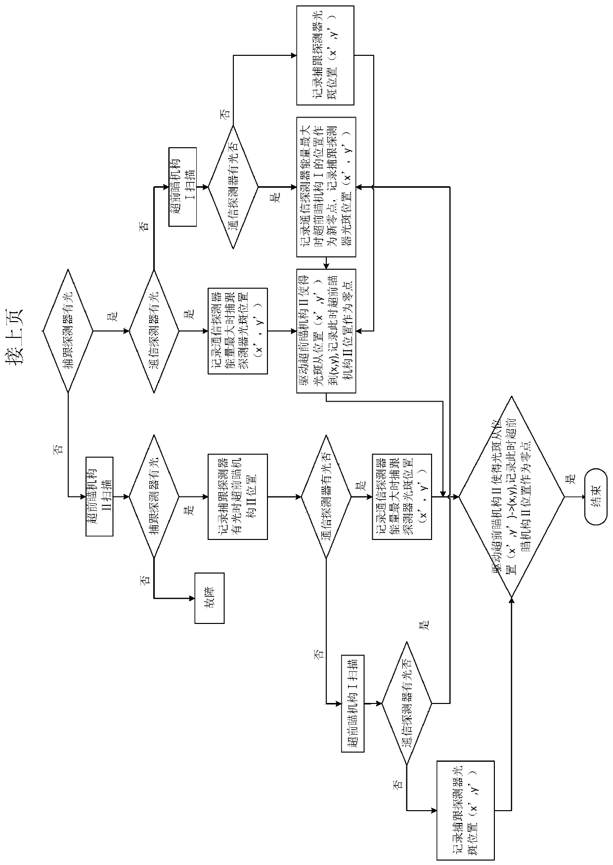
[0051] The on-orbit calibration of the satellite optical communication terminal and the method for calibrating the coaxiality of transmission and reception of the present invention will be described in detail below with reference to specific embodiments and FIG. 2 .

[0052] In order to realize the functions of on-orbit self-calibration and optical axis correction of satellite laser communication equipment, the on-orbit self-calibration of the satellite optical communication terminal of the present invention mainly revolves around the calibration of the receiving optical axis position of the beacon laser and the signal laser and the correction of the transmitting optical axis position Two aspects, according to its working process, can be divided into two stages, that is, the stage of externally calibrated receiving optical axis and the stage of internally correcting emitting optical axis.

[0053] 1) External calibration receiving optical axis stage

[0054] 1.1) The ground sa...


PUM


Abstract

In the prior art, a satellite optical communication terminal is calibrated in an on-orbit manner through a laser communication ground station. The position of the receiving optical axis can only be calibrated at night; the transmitting-receiving coaxiality of the terminal itself cannot be corrected; the terminal cannot be caught; the communication state is checked; The invention provides a satellite optical communication terminal in-orbit calibration and transceiving coaxiality correction device and method. The device comprises an external calibration transmitting branch, The system comprisesa calibration reflector, a coarse pointing mechanism, an optical antenna, a fine pointing mechanism, a beam splitter I, a beam splitter II, a beam splitter III, an advanced aiming mechanism I, a signal internal calibration transmitting branch, an advanced aiming mechanism II, a beacon internal calibration transmitting branch, a communication receiving branch, a communication detector, a capturingand receiving branch, a capturing and tracking detector, a communication transceiver and a terminal controller. The device and the method can meet the requirement of on-orbit self-calibration of the satellite laser communication terminal, and the coaxiality of the correction transmit-receive optical axis can reach the micro-radian magnitude.

Description

technical field [0001] The invention belongs to a space laser communication technology, and mainly relates to a device and method for on-orbit calibration of a satellite optical communication terminal and correction of coaxiality of sending and receiving. Background technique [0002] Generally, the light divergence angle of the beacon signal of a satellite optical communication terminal is only a few hundred or even tens of microradians, so the coaxiality of the optical system must be controlled within a few microradians. Factors such as the launch of the laser communication terminal on the ground with the space platform, the violent vibration in orbit, and the thermal deformation after orbit may affect the coaxiality of the receiving and receiving optical axes of the optical system. For two-way full-duplex satellite laser communication equipment, The coaxiality of the optical system for transmitting and receiving determines whether the terminals of both parties can normall...

Claims


Application Information

Patent Timeline
IPC IPC(8): H04B10/118H04B10/077
Inventor 夏方园杨建峰幺周石任斌李帅张文睿
Owner XI'AN INST OF OPTICS & FINE MECHANICS - CHINESE ACAD OF SCI
Learn More