Diaphragm pumps for fluidizing and conveying powders

一种膜片式、粉末的技术,应用在用于弹性流体的泵送装置的部件、变容式泵部件、液体变容式机械等方向,能够解决大小或者说尺寸获得等问题,达到涂油均匀、的磨损的效果

Active Publication Date: 2021-12-03
DIPL ING ERNST SCHMITZ GMBH & CO KG MASCH & APP
View PDF3 Cites 0 Cited by
  • Summary
  • Abstract
  • Description
  • Claims
  • Application Information

AI Technical Summary

Problems solved by technology

The robust materials described are only available in flat or plate-like structures and not in the required sizes or dimensions

Method used


Image

  • Diaphragm pumps for fluidizing and conveying powders

Examples


Embodiment Construction

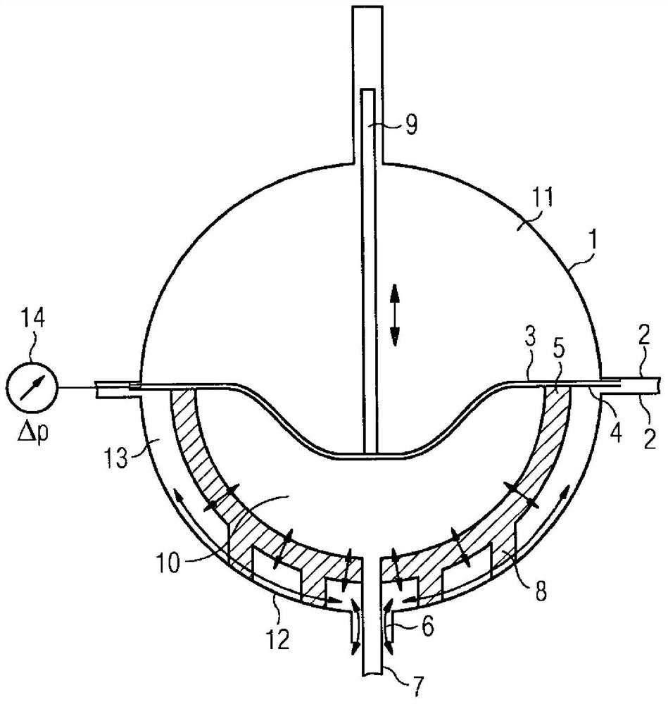
[0014] exist figure 1 The diaphragm pump shown in is a device comprising two pressure-resistant half shells 1 , 12 which are gas-tightly connected to each other via a flange connection 2 . In addition to the simple assembly possibilities of the powder pump, the flange connection also has the additional function of fixing and clamping the membrane 3 and the loose surface 5 via the filter flange 4 . Due to the spherical geometry, the membrane can thus be deflected advantageously and in a manner that preserves the filter material into the powder chamber in the form of a paraboloid of revolution. In this case, the deflection of the diaphragm is brought about by the force action of the hydraulic fluid, as described, for example, in DE 10 2016 201 182 . Jumpy changes are avoided and a substantially flat contact of the membrane 3 against the half-shell-shaped loose surface 5 can be achieved after the delivery process has ended. A small dead volume can be achieved by this advantageo...


PUM


Abstract

The invention relates to a diaphragm pump for fluidizing and conveying powders, the pressure-resistant housing of which consists of two half-shells (1, 12) with a first flange The connecting structure (2) is connected and the diaphragm (3) and the loose face (5) for the input of vortex or pressurized gas to the diaphragm pump are connected into the two half-shells with a second flange. In pressure vessels, wherein a uniform gas supply is achieved via a half-shell-shaped loose surface (5) designed to be gas-permeable, and the filter material used for the loose surface (5) consists of a filter material with a sufficiently small pore size and a filter fineness < 20 μm Porous metal composition.

Description

technical field [0001] The invention relates to a diaphragm pump for fluidizing and conveying powders. Background technique [0002] The body produced according to the method according to the invention can advantageously be used as a filter element in diaphragm pumps for fluidizing and pressurizing pulverulent products, such as pulverized coal, by means of an inert gas at a pressure of up to 7 MPa Used as loose surface. [0003] The continuous and economical conveying of dense flows is of increasing importance when the powder quality of pulverized fuels for coal and biomass gasification plants varies, in order, for example, to operate gasification plants more economically and with high availability. This target setting is achieved in a particular way using a diaphragm pump as proposed in patent application DE102016201182 of 27.01.2016. Here, the pulverulent conveyed material is sucked from below into a diaphragm pump, pressurized and fluidized in a further step, and then d...

Claims


Application Information

Patent Timeline
Patent Type & Authority Patents(China)
IPC IPC(8): B01D39/20
CPCB01D2239/10B01D2239/1216B01D39/2051F04B43/02F04B43/06F04B53/22
Inventor F·汉内曼S·拉姆M·韦德
Owner DIPL ING ERNST SCHMITZ GMBH & CO KG MASCH & APP
Why Eureka
Try Eureka