High-speed communication method and high-speed communication system

A high-speed communication and analog signal technology, applied in the baseband system, transmission system, digital transmission system, etc., can solve the problems of alienation, communication interruption, high cost, etc., and achieve the effect of good operability, easy implementation, and low cost

Inactive Publication Date: 2019-05-21
福井诚司
View PDF19 Cites 0 Cited by
  • Summary
  • Abstract
  • Description
  • Claims
  • Application Information

AI Technical Summary

Problems solved by technology

[0005] In addition, in order to increase the communication speed, it is necessary to develop communication software. At the same time, in terms of hardware, in addition to the method of increasing the transmission speed (frequency), it is also considered, for example, to expand the signal bandwidth or increase the S / N ratio. Utilize techniques such as parallel transmission circuits using multiple transmission circuits in parallel, but since considerable time and cost are required with the development of equipment, this system cannot be expected to achieve immediate results in terms of realizability, and further, even if Realization also has the disadvantage of high cost
[0006] In addition, regarding this high-speed communication, as described above, compared with the past, the transmission speed has been improved considerably. However, if a major disaster such as an earthquake occurs, the amount of calls between users will temporarily increase, so that Insufficiency of the communication capacity causes the communication to be blocked, so that the required communication cannot be performed when necessary, and such fundamental problems have not yet been completely resolved.
[0007] That is to say, in the current high-speed communication system, it is only in name only, and at the time of the above-mentioned disasters, there are communications of the police, the Self-Defense Forces, firefighting, administrative organizations, etc. Defects

Method used


Image

  • High-speed communication method and high-speed communication system
  • High-speed communication method and high-speed communication system
  • High-speed communication method and high-speed communication system

Examples


Embodiment Construction

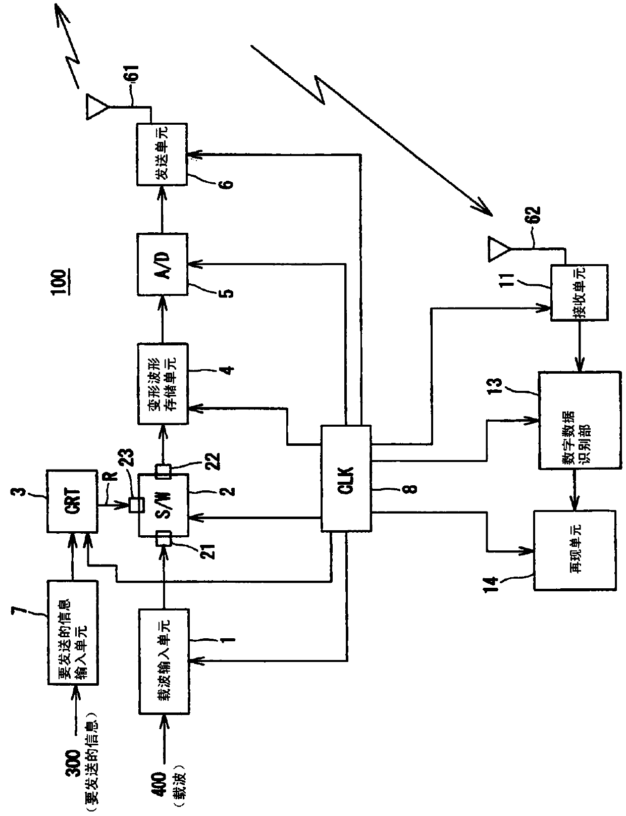
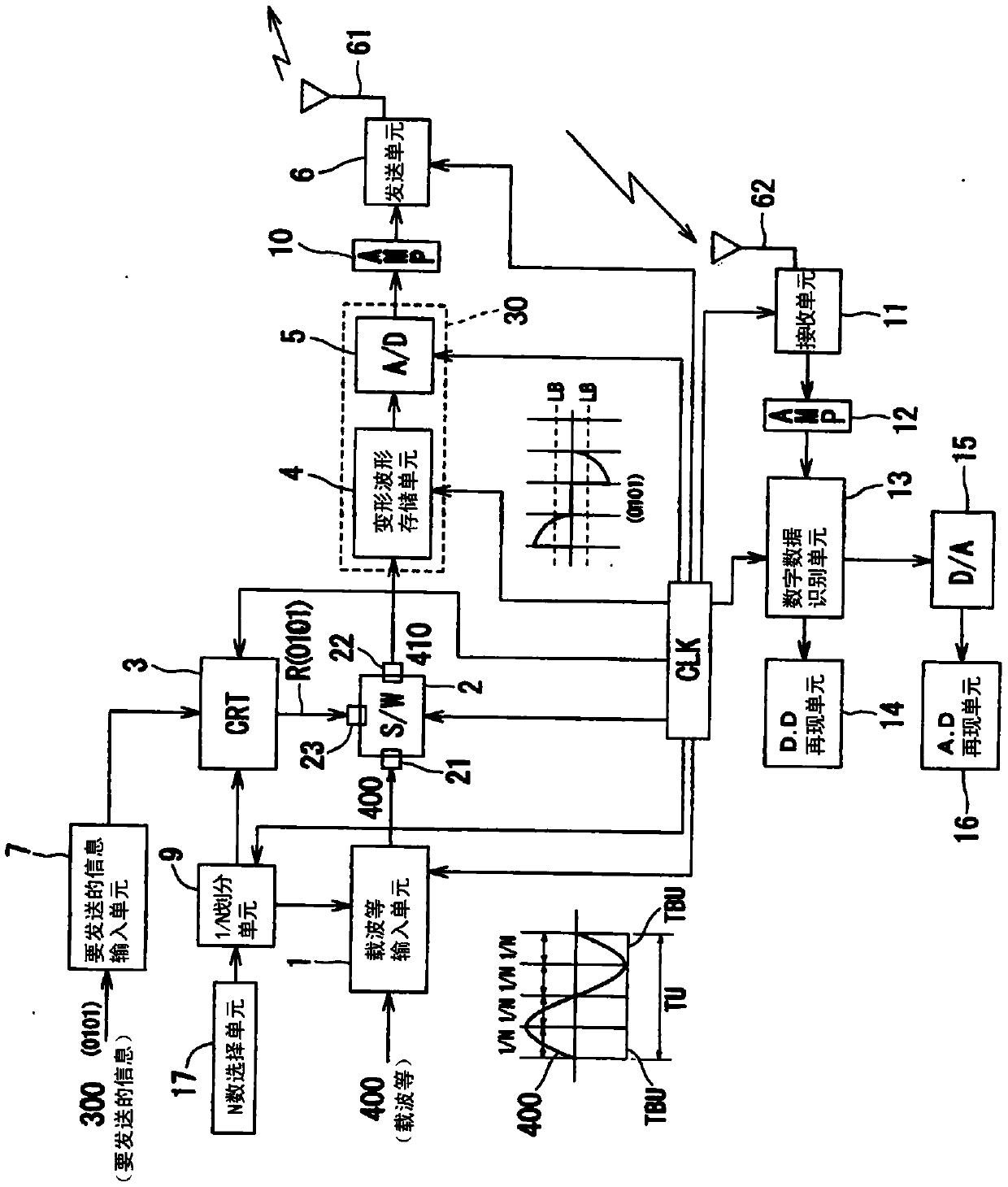
[0035] The configuration examples of each specific example of the high-speed communication method and the high-speed communication system of the present invention will be described in detail below with reference to the drawings.

[0036] First, an example of a specific configuration of the high-speed communication method as the first aspect of the present invention will be described.

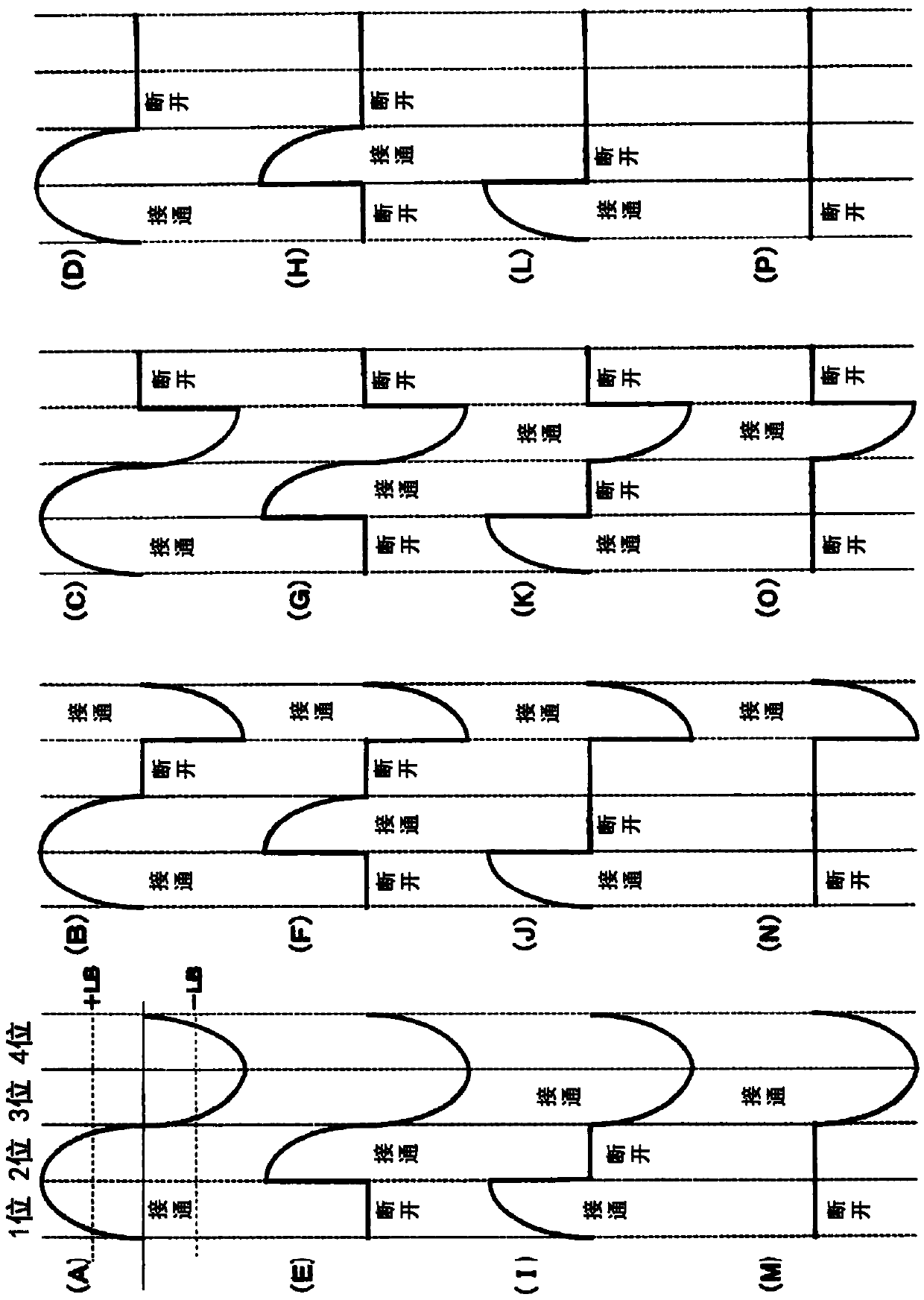
[0037] which is, figure 1 The structure of a specific example of the high-speed communication method 100 as the first aspect of the present invention is shown. In the figure, the high-speed communication method 100 is shown, which is characterized in that the unit of the analog waveform signal of the carrier wave or the fundamental frequency wave 400 The waveform in the cycle time is deformed in response to the digital signal 300 of the information BD to be transmitted.

[0038] That is to say, it relates to a high-speed communication method or high-speed communication system 100 based on the f...


PUM


Abstract

The purpose of the present invention is to provide a high-speed communication method and a high-speed communication system, capable of resolving problems in the prior art, achieving good operability with a simple configuration and at a low cost without requiring major modification or replacement of existing communication-related equipment, and being able to be implemented in a short period of time. In the high-speed communication method and the high-speed communication system (100), a waveform in a unit period time of an analog waveform signal for a carrier wave or a fundamental frequency wave(400) is transformed in response to a digital signal (300) for information BD to be transmitted.

Description

technical field [0001] The present invention relates to a high-speed communication method and a high-speed communication system. More specifically, it relates to a data processing device with a simple structure, which is not expected to be delicate, complex and expensive, and a further improvement of a transmission device that does not require new equipment and is operable. A high-speed communication method and a high-speed communication system capable of high-speed communication are desirable, inexpensive, and economical. Background technique [0002] In the past, regardless of wired or wireless, operations to easily and freely send and receive various information have been frequently performed. With the development and progress of communication technology, opportunities to frequently send and receive various types of large amounts of information have expanded, and its importance will continue to rise in the future. direction of increase. [0003] In addition, especially i...

Claims


Application Information

Patent Timeline
Patent Type & Authority Applications(China)
IPC IPC(8): H04L27/02
CPCH03C5/00H04L27/02H04L27/04H04L27/06H03M1/12H04L25/03847H04L25/4906
Inventor 福井诚司
Owner 福井诚司
Why Eureka
Try Eureka