Aerosol discharge system

An aerosol and electrode technology, which is used in electrostatic and electrical components to achieve the effect of solving safety problems

Inactive Publication Date: 2007-03-07
TSINGHUA UNIV +1
View PDF0 Cites 3 Cited by
  • Summary
  • Abstract
  • Description
  • Claims
  • Application Information

AI Technical Summary

Problems solved by technology

[0005] The purpose of the present invention is to provide a device for eliminating electricity in aerosols by using electrostatic electricity elimination technology, so as to solve many safety problems existing in the use of radioactive sources in the prior art, and at the same time make it simple in structure, easy to operate, and low in investment. and low maintenance costs

Method used


Image

  • Aerosol discharge system

Examples


Embodiment Construction

[0013] The principle, structure and working process of the present invention will be further described below in conjunction with the accompanying drawings.

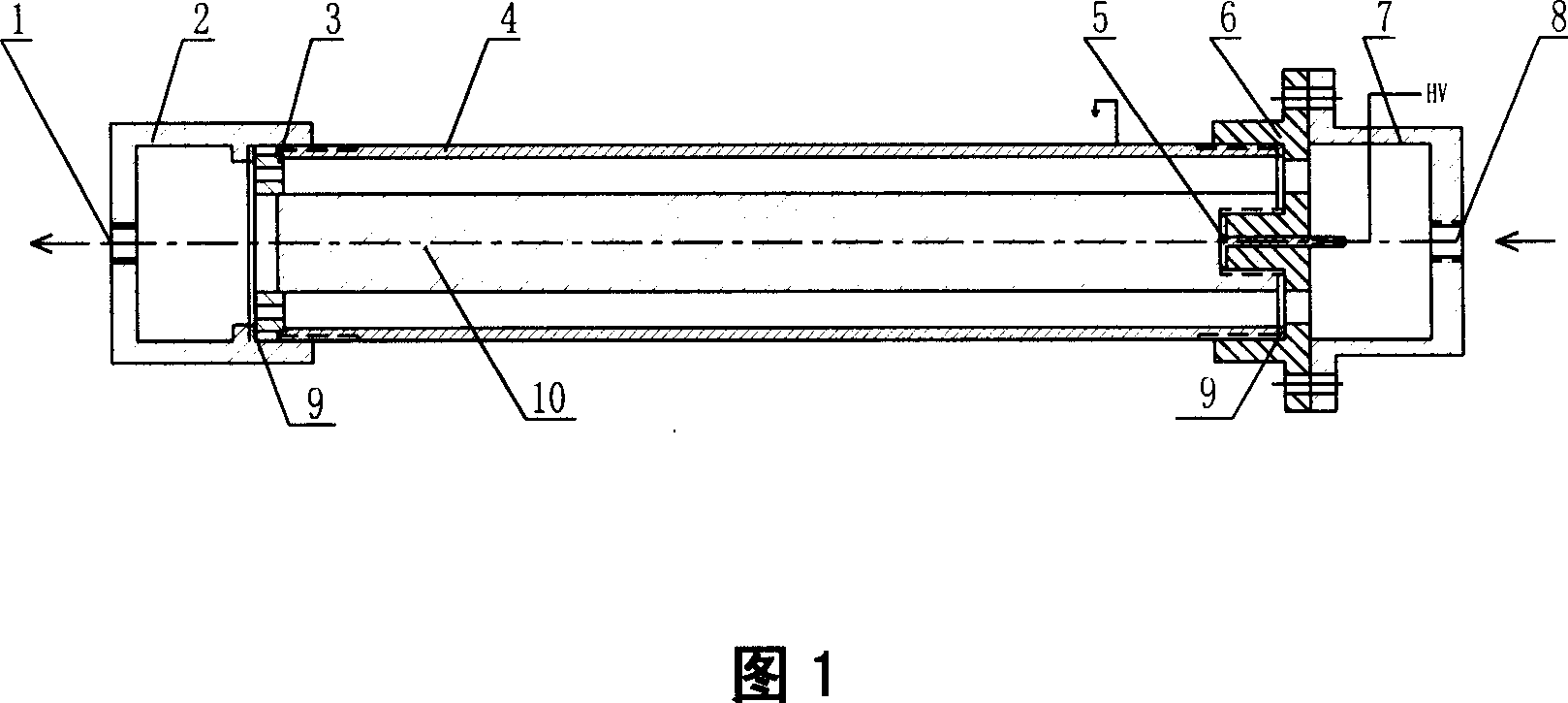
[0014] Fig. 1 is a schematic structural view of an embodiment of an aerosol power elimination device provided by the present invention. The device comprises an inner shaft electrode 10, an outer cylinder electrode 4 arranged concentrically with the inner shaft electrode, a front support 6 and a rear support 3 for supporting the inner shaft electrode, a front end cover 7 and a rear end cover 2 arranged at both ends of the electrode; The front and rear brackets are respectively provided with through holes, and the front and rear end covers are respectively provided with an aerosol air inlet 8 and an air outlet 1, and a conductive probe 5 is embedded in the inlet end of the inner axis electrode. Connected to the current power supply, and the outer cylinder electrode is grounded. The rear end cover 2 is connected to the oute...


PUM


Abstract

This invention relates to gas melt deionization device with high voltage and field charge, which comprises the following parts: inner axis electrode distributed with outside electrode to support inner axis electrode front and back rack; front and back end cover set on both ends of electrodes; holes on front and back rack with gas melt entrance and exit holes with one conductive detector imbedded at inner axis electrode entrance end connected to the high voltage power; the outside cylinder electrode is connected to earth to form high voltage field.

Description

technical field [0001] The invention relates to an electricity dissipating device, in particular to a device which utilizes a high-voltage electric field to eliminate charges carried by charged aerosols. Background technique [0002] Aerosol is a dispersion system formed by dispersing liquid or solid particles with a diameter of 0.002-100 μm in a gas medium. Aerosols have a large specific surface area and may be charged in a variety of ways. The amount of charge varies and changes with time. The positive and negative charges depend on the external environmental conditions. In various operations such as measuring instrument calibration or filter product performance testing, it is necessary to use uncharged or steady-state single-charged aerosols. At this time, the charged aerosol must be de-energized before calibration or testing operations. . [0003] At present, there are mainly three kinds of aerosol neutralization technologies in the prior art: radiation neutralization ...

Claims


Application Information

Patent Timeline
IPC IPC(8): H05F3/00
Inventor 江锋张振中张力生
Owner TSINGHUA UNIV
Why Eureka
Try Eureka