Dredging type silt cleaning device

A technology for cleaning equipment and silt, applied in the direction of earth mover/shovel, construction, etc., can solve problems such as threats to the life and property safety of residents, increase in river dredging construction, and poor drainage.

Inactive Publication Date: 2019-05-24
HUAINAN ZHONGXING MACHINERY MFG
View PDF7 Cites 6 Cited by
  • Summary
  • Abstract
  • Description
  • Claims
  • Application Information

AI Technical Summary

Problems solved by technology

[0002] Serious river siltation leads to poor discharge, which will cause floods to directly hit the embankment, seriously threatening the lives and property safety of local residents. The smoothness of the river directly affects the flood discharge and flood control function of the river, especially in the annual flood season. The level of requirements is higher. People realize that it is urgent to dredge the river. However, due to the influence of the river's own factors and the influence of the buildings on both sides and the erection of bridges, it is very difficult for the dredging construction of the river. Therefore, a dredging is developed. The device can efficiently carry out dredging work
[0003] Publication No. CN105672390B provides a river chain bucket dredger and its dredging construction method. This device drives the lower mud bucket into the river channel through the transmission chain to contact with the silt for dredging and dredging. This dredging method requires The mud bucket is directly inserted into the silt, and when the mud hopper moves out of the silt, it will exert a large shear force on the transmission chain, and then the work is unstable in the long-term dredging working environment, and when the silt is salvaged Unable to automatically discharge the silt after reaching the hull

Method used


Image

  • Dredging type silt cleaning device
  • Dredging type silt cleaning device
  • Dredging type silt cleaning device

Examples


Embodiment

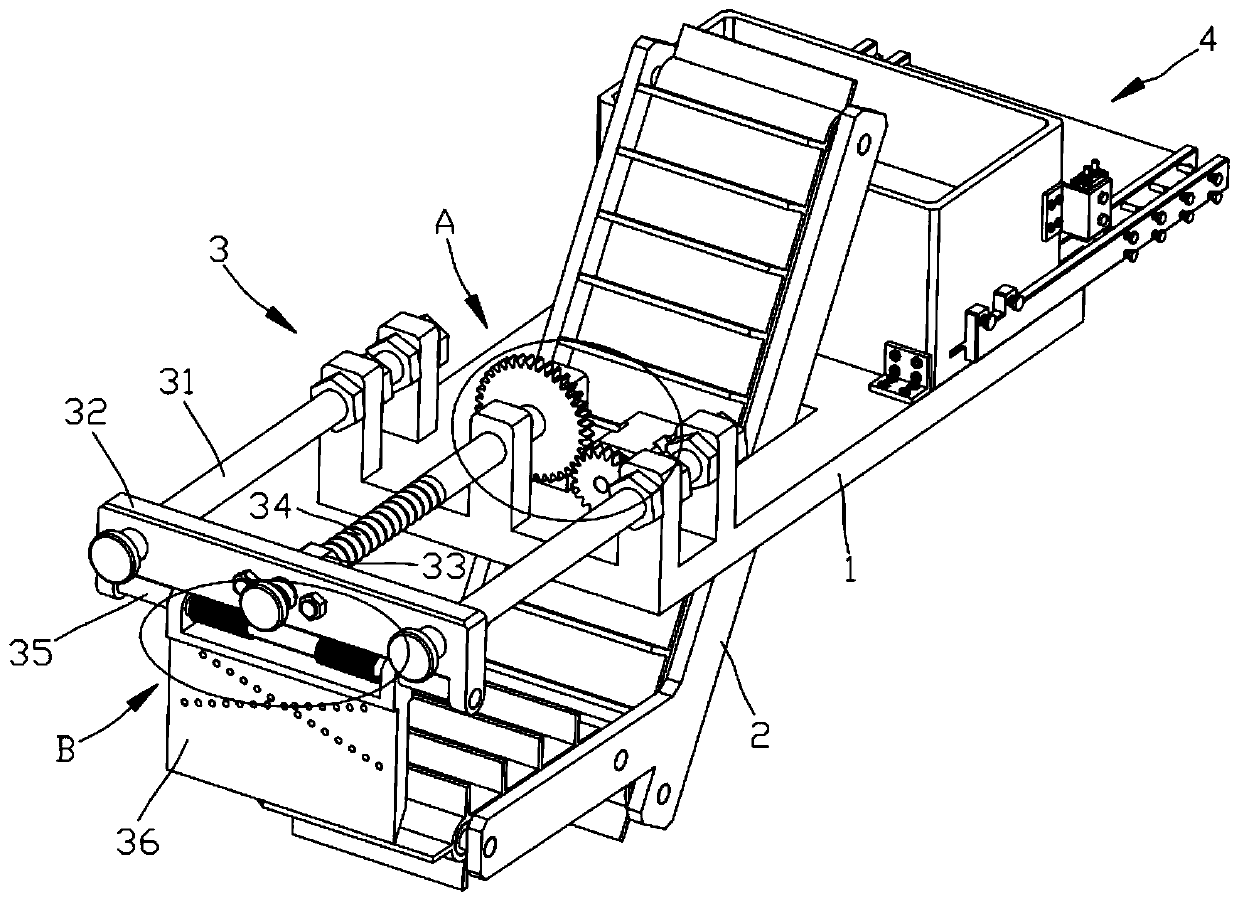
[0025] see Figure 1 to Figure 5 , the present invention provides a technical solution:

[0026] A dredging type sludge cleaning device, including a hull 1, a lifting conveyor belt 2, a dredging mechanism 3 and a transfer mechanism 4, wherein:

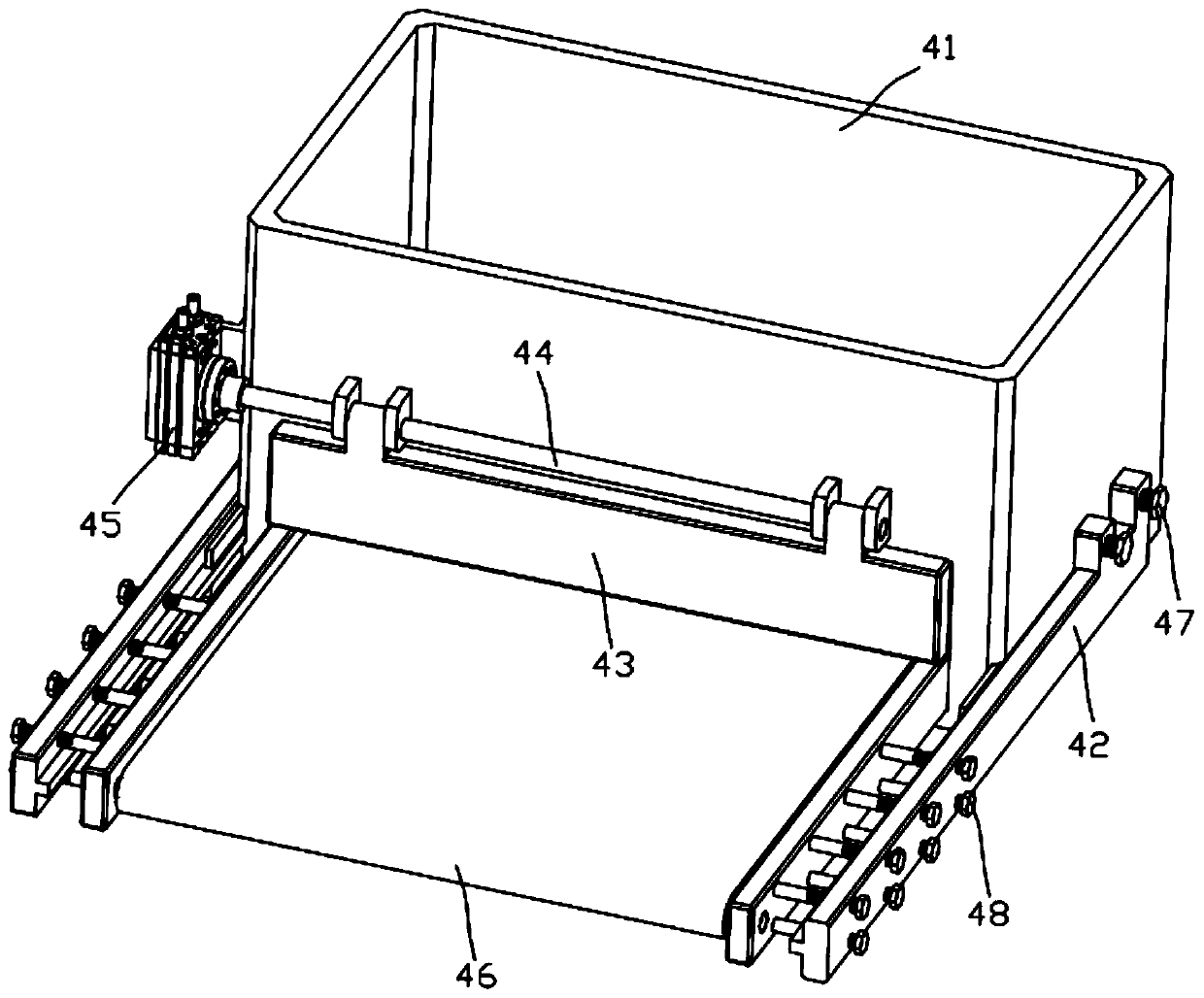
[0027] The conveyor belt 2 is fixedly installed on the hull 1, and the conveyor belt 2 is divided into a feed end and a discharge end, wherein the feed end of the conveyor belt 2 is located below the shovel plate 36, and the discharge end of the conveyor belt 2 is located at the receiving hopper 41 above;

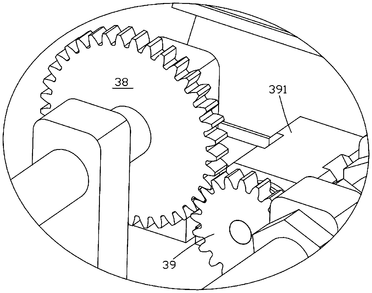
[0028] Dredging mechanism 3 comprises support rod 31, slide block 32, sleeve 33, screw mandrel 34, connecting shaft 35, shovel plate 36, torsion spring 37, bull gear 38, pinion 39 and motor 391, two support rods 31 respectively It is fixedly installed on the front support frame of the hull 1 by bolts, and the two ends and the middle of the slide block 32 are provided with round holes, wherein the round holes at the two ends of the...


PUM


Abstract

The invention provides a dredging type silt cleaning device. The dredging type silt cleaning device comprises a ship body, a lifting conveyor belt, a dredging mechanism and a transfer mechanism; the dredging mechanism comprises supporting rods, a sliding block, a sleeve, a lead screw, a connecting shaft, a shovel plate, torsional springs, a big gear, a small gear and a motor; the sliding block isinstalled on the ship body through the supporting rods; one end of the lead screw is installed on the ship body, the other end of the lead screw penetrates through the sleeve and the sliding block, and the lead screw is in power connection with the motor; the shovel plate is rotatably installed on the sliding block through the connecting shaft; and the transfer mechanism is fixedly installed on the ship body. The rotation movement between the lead screw and the sleeve is transformed into linear movement, and then the shovel plate is pushed to dredge silt; the shovel plate can rotate around thesliding block, and then the shovel plate is folded when the shovel plate move towards a silt stack; the shovel plate is prevented from generating counter-acting force by being in contact with the silt stack, and then it is ensured that the ship body cannot tempestuously waggle when dredging is carried out; and the silt is automatically transported outside of the ship body through the transfer mechanism, and the dredged silt is prevented from being transferred through manual work.

Description

technical field [0001] The invention relates to the technical field of underwater dredging, in particular to a dredging type sludge cleaning device. Background technique [0002] Severe siltation of the river channel leads to poor discharge, which will cause floods to directly impact the river embankment, seriously threatening the lives and property safety of local residents. The level of requirements is higher. People realize that it is urgent to dredge the river. However, due to the influence of the river's own factors and the influence of the buildings on both sides and the erection of bridges, it is very difficult for the dredging construction of the river. Therefore, a dredging is developed. The device can efficiently carry out dredging work. [0003] Publication No. CN105672390B provides a river chain bucket dredger and its dredging construction method. This device drives the lower mud bucket into the river channel through the transmission chain to contact with the si...

Claims


Application Information

Patent Timeline
Patent Type & Authority Applications(China)
IPC IPC(8): E02F5/28E02F7/02
Inventor 牛其刚闵猛闵珑鑫朱梦
Owner HUAINAN ZHONGXING MACHINERY MFG
Why Eureka
Try Eureka