
Electromagnetic heating equipment temperature measuring system and method and electromagnetic heating equipment

A heating equipment and electromagnetic technology, applied in the field of electromagnetic heating equipment and electromagnetic heating equipment temperature measurement system, can solve the problems of difficult transmission of temperature sensor signals to control circuits, increased cost, and easy damage.

Inactive Publication Date: 2019-05-24
MIDEA GRP CO LTD
View PDF7 Cites 0 Cited by
  • Summary
  • Abstract
  • Description
  • Claims
  • Application Information

AI Technical Summary

Problems solved by technology

[0005] 1. Open a hole in the glass panel, and extend the temperature sensor from the surface of the panel to directly contact the bottom of the pot. This solution destroys the existing structure of the glass panel, and there is a risk of water penetrating into the circuit board, reducing the mechanical strength of the glass panel.
[0006] 2. The glass panel does not have a hole, but forms a bulge in a certain way, and it is difficult for the signal of the temperature sensor to be transmitted to the control circuit in this solution
[0007] 3. The glass panel directly forms a bulge, which does not require openings and leads are more convenient. However, this solution puts forward new requirements for the manufacturing process of the glass panel, which greatly increases the cost and is difficult to popularize and apply. The raised glass panel collides with the pot. easily damaged

Method used


Image

  • Electromagnetic heating equipment temperature measuring system and method and electromagnetic heating equipment
  • Electromagnetic heating equipment temperature measuring system and method and electromagnetic heating equipment
  • Electromagnetic heating equipment temperature measuring system and method and electromagnetic heating equipment

Examples


Embodiment Construction

[0033] The specific implementation manners of the embodiments of the present invention will be described in detail below in conjunction with the accompanying drawings. It should be understood that the specific implementation manners described here are only used to illustrate and explain the embodiments of the present invention, and are not intended to limit the embodiments of the present invention.

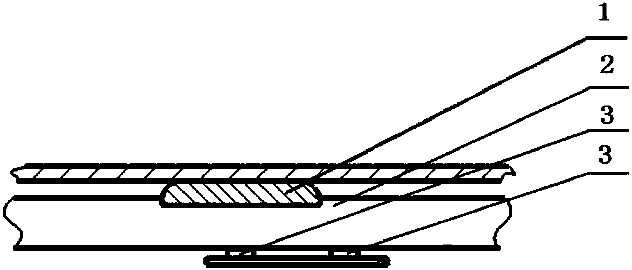
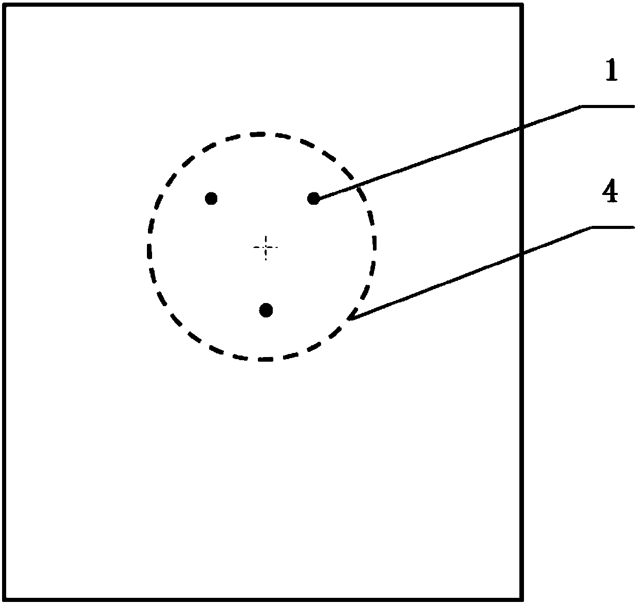
[0034] figure 1 It is a structural schematic diagram of an electromagnetic heating equipment temperature measurement system provided by an embodiment of the present invention. Such as figure 1 As shown, for the sake of illustration, figure 1 The structure of two temperature sensors 3 in a group of temperature sensors 3 corresponding to one heat conduction bump 1 is shown, and the structures of other heat conduction bumps 1 and temperature sensors 3 are similar.

[0035] The electromagnetic heating equipment includes a glass panel 2, and the system includes: at least one heat co...


PUM


Abstract

The embodiment of the invention provides an electromagnetic heating equipment temperature measuring system and method and electromagnetic heating equipment and belongs to the field of household appliances. The electromagnetic heating equipment comprises a glass panel. The system comprises at least one heat conducting bumping point and at least one group of temperature sensors, wherein the at leastone heat conducting bumping point protrudes out of the surface of the glass panel so as to support cookware arranged on the electromagnetic heating equipment; and each group of temperature sensors ofthe at least one group of temperature sensors comprises at least two temperature sensors, each group of the temperature sensors is fixed to the lower portion of the glass panel, the first temperaturesensor in each group of temperature sensors is arranged in a position right facing the midpoint of the heat conducting bumping point, and the distances between the first temperature sensor and the other temperature sensors in each group of temperature sensors are different. According to the electromagnetic heating equipment temperature measuring system and method and the electromagnetic heating equipment, temperature measuring is safe and accurate, signal transmission is good, and temperature measuring response is extremely quick.

Description

technical field [0001] The invention relates to household appliances, in particular to a temperature measuring system and method for electromagnetic heating equipment and electromagnetic heating equipment. Background technique [0002] The current electromagnetic heating equipment generally adopts glass-ceramic as the panel, and the glass panels are all flat and smooth. The temperature measurement of the cooker of the electromagnetic heating equipment mainly adopts the "built-in" temperature sensor, that is, the temperature sensor is installed under the back of the microcrystalline panel. [0003] Because there is a layer of glass panel between the temperature sensor and the pot, and the thermal conductivity of the glass panel is poor, there is often a large deviation between the measured temperature and the actual temperature of the pot (it can reach tens or even hundreds of times). degrees Celsius). The direct consequence is that the electromagnetic heating equipment can...

Claims


Application Information

Patent Timeline
Patent Type & Authority Applications(China)
IPC IPC(8): F24C7/08
Inventor 黄新建伍叔云严平高安平张军歌申晓雷
Owner MIDEA GRP CO LTD
Learn More