Relay protection method for protecting transformer from being damaged by flashover of circuit breaker

A flashover protection and relay protection technology, applied in emergency protection circuit devices, electrical components, etc., can solve the problems of transformer damage, transformer damage, long delay in failure protection, etc., to achieve great application value and avoid transformer damage.

Active Publication Date: 2019-05-24
XIAN THERMAL POWER RES INST CO LTD +1
View PDF1 Cites 2 Cited by
  • Summary
  • Abstract
  • Description
  • Claims
  • Application Information

AI Technical Summary

Problems solved by technology

According to the provisions of GB1094.5-2008 "Power Transformer Part 5: Capability to Withstand Short Circuit", transformers with a capacity above 2500kVA should not be damaged when the short circuit delay is not greater than 250ms, that is, if the accident lasts longer than 250ms, it may be damaged. damage to the transformer
Moreover, for flashover faults, because the voltage phases on both sides of the fracture are opposite, the current flowing through the transformer is twice the short-circuit current when the power supplies on both sides are in the same phase, which will cause huge damage to the transformer in a short time
[0008] In 2012, about 9 seconds after the generator of a power plant in Jiangsu Province was decoupled from the system, a flashover occurred on phase A of the high-voltage side switch

Method used


Image

  • Relay protection method for protecting transformer from being damaged by flashover of circuit breaker
  • Relay protection method for protecting transformer from being damaged by flashover of circuit breaker
  • Relay protection method for protecting transformer from being damaged by flashover of circuit breaker

Examples


Example Embodiment

[0042] The present invention will be further described below in conjunction with the accompanying drawings.

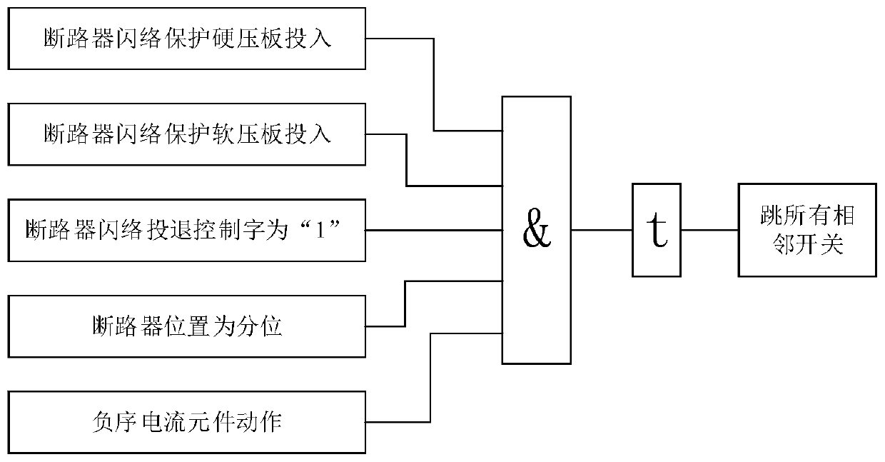
[0043] like figure 1 As shown, a kind of relay protection method that prevents the transformer from being damaged due to circuit breaker flashover provided by the present invention, the specific process is as follows:

[0044] 1. The protection device judges whether the flashover protection hard pressure plate of the circuit breaker is engaged.

[0045] 2. The protection device judges whether the flashover protection soft pressure plate of the circuit breaker is engaged.

[0046] 3. The protection device judges whether the flashover switching control word is set to "1".

[0047] 4. The protection device judges whether the position of the circuit breaker is in the sub-position.

[0048] 5. When steps 1, 2, 3, and 4 are all satisfied, the protection device collects the negative sequence current passing through the circuit breaker to meet the operating conditions, and ...


PUM


Abstract

The invention discloses a relay protection method for protecting a transformer from being damaged by the flashover of a circuit breaker. The method protects all adjacent circuit breakers of a circuitbreaker with flashover, and the circuit breaker failure protection is not started. The protection method is suitable for the protection of a grid-connected circuit breaker at a high-voltage side of atransformer of a generator-transformer bank without a machine-end circuit breaker, and the delay of the protection action is 100ms, so that all adjacent circuit breakers of the circuit breaker with the flashover can be tripped off within 250ms. An existing protection method is usually longer in time delay from the starting of circuit breaker flashover protection to an outlet of failure protection,which usually causes the damage to a transformer. The method integrates the circuit breaker protection and the transformer protection, so after the flashover of the circuit breaker, all adjacent circuit breakers are directly tripped off, thereby achieving the isolation of a fault within 250ms, avoiding the expansion of the fault range, and guaranteeing that the transformer is not damaged. The method is supported by the theory and test of the national standard: the fifth part of a GB1094.5-2008 power transformer: the capability for bearing the short circuit fault, and has a great application value.

Description

technical field [0001] The invention belongs to the technical field of relay protection for power systems, and in particular relates to a relay protection method for preventing transformers from being damaged due to circuit breaker flashover. Background technique [0002] When the generator-transformer unit is connected to the grid through the circuit breaker on the high-voltage side of the step-up transformer, the voltage difference on the breaker breaker changes continuously with the angular difference between the system voltage on both sides of the breaker and the no-load voltage of the generator-transformer unit. Change, when a certain phase angle difference is 180°, a voltage difference of twice the operating voltage will appear on both sides of the fracture. At this time, if the internal insulation of the circuit breaker is defective or the external insulation is polluted, it is very easy to develop into a circuit breaker flashover accident. Some domestic power plants...

Claims


Application Information

Patent Timeline
IPC IPC(8): H02H7/04H02H7/22
Inventor 吴易洋杨博薛磊兀鹏越
Owner XIAN THERMAL POWER RES INST CO LTD
Why Eureka
Try Eureka