motor base

A technology of motor base and motor connector, which is applied in the direction of electromechanical devices, electrical components, electric components, etc., can solve the problems of motor base deformation, large force, damage, etc., and achieve the effect of avoiding damage to the motor base

Active Publication Date: 2020-05-19
WUHAN MARINE MACHINERY PLANT
View PDF4 Cites 0 Cited by
  • Summary
  • Abstract
  • Description
  • Claims
  • Application Information

AI Technical Summary

Problems solved by technology

[0003] However, when the power of the motor is too large for the motor base of this structure, the motor base will be greatly deformed or damaged due to the excessive force of the motor acting on the motor base.

Method used


Image

  • motor base
  • motor base
  • motor base

Examples


Embodiment Construction

[0024] In order to make the object, technical solution and advantages of the present invention clearer, the embodiments of the present invention will be further described in detail below in conjunction with the accompanying drawings.

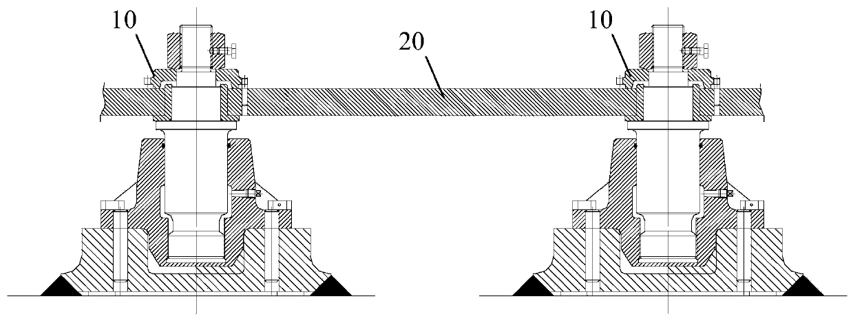
[0025] figure 1 is a schematic structural diagram of the motor base provided by the embodiment of the present invention. Such as figure 1 As shown, the motor base includes two support units 10 and a motor connecting plate 20 . Two support units 10 are arranged at intervals.

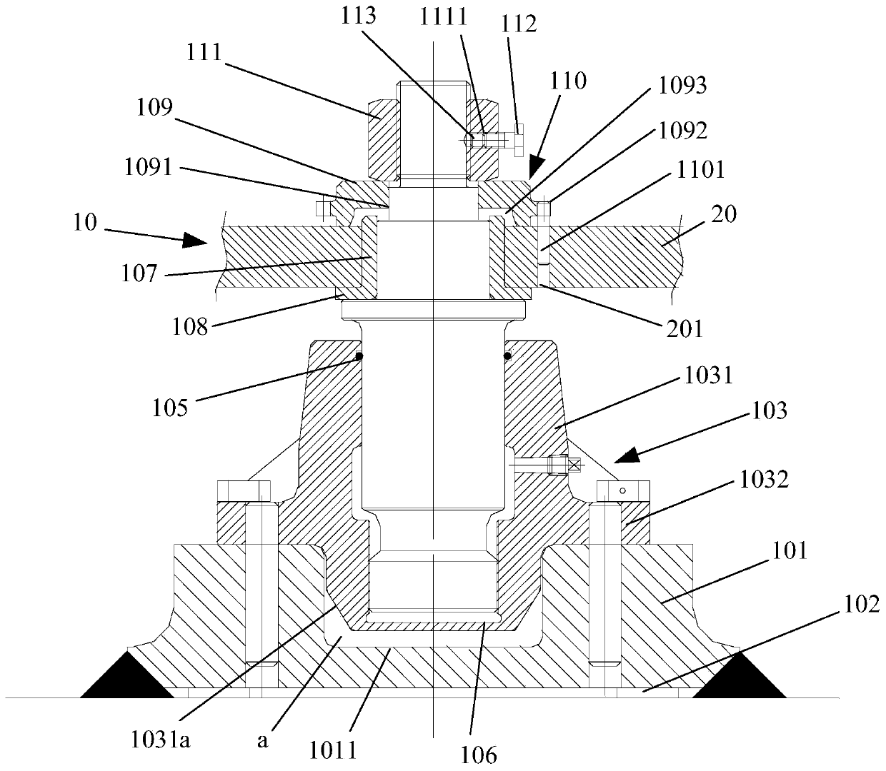
[0026] figure 2 is a schematic structural view of the support unit provided by the embodiment of the present invention, such as figure 2 As shown, each support unit 10 includes a chassis 101, a shock absorber 102, an intermediate seat 103 and a connecting shaft 104, the shock absorber 102 is arranged at one end of the chassis 101, and the intermediate seat 103 includes a sleeve 1031 connected with the coaxial The connecting plate 1032 on the sleeve 1031, the connecti...


PUM


Abstract

The invention discloses a motor base, and belongs to the field of mechanical equipment. Two supporting units in the motor base are spaced apart from each other. The damping gasket of a chassis in thesupporting units is arranged close to a platform. A middle base and a connecting shaft are sequentially installed on the chassis. The connecting shaft is connected with the connecting plate of a motor. The motor is installed between the two supporting units through a motor connecting piece. The acting force of the motor is borne by the two supporting units. Therefore, the risk that the motor baseis damaged due to the fact that the borne acting force is too large is reduced. Meanwhile, the damping gasket between the chassis and the platform can also play a role in preventing the acting force acting on the motor base from being too large. The connecting plate of the middle base is fixed on the chassis. One end of a sleeve is inserted into the groove in the chassis. A buffer space is arranged between the end face, close to a groove, of the sleeve and the groove. The buffer space between the sleeve and the base plate can play a role in relieving force to a certain extent. The problem thatthe motor base is damaged due to the facts that the acting force borne by a supporting base is excessively concentrated and the acting force of the motor changes too fast is solved.

Description

technical field [0001] The invention relates to the field of mechanical equipment, in particular to a motor base. Background technique [0002] The motor base is used to install and fix the motor, which is an important structure to ensure the stable operation of the motor. The current motor base usually includes a mounting chassis and a connecting piece, the mounting chassis is in direct contact with the motor chassis on the motor, and the connecting piece connects and fixes the mounting chassis and the motor chassis so that the motor can work smoothly on the motor base. [0003] However, when the power of the motor is too large for the motor base of this structure, the motor base will be greatly deformed or damaged due to the excessive force exerted by the motor on the motor base. Contents of the invention [0004] The embodiment of the present invention provides a motor base, which can effectively disperse the force to be borne by the motor base, and reduce the possibil...

Claims


Application Information

Patent Timeline
IPC IPC(8): H02K5/00H02K5/24
Inventor 程旎王正白福余席志成
Owner WUHAN MARINE MACHINERY PLANT
Why Eureka
Try Eureka