
Transmission for a motor vehicle

A technology of transmission and motor vehicle, applied in the field of power transmission system, can solve problems such as affecting the service life of multi-plate clutches

Active Publication Date: 2019-05-24
ZF FRIEDRICHSHAFEN AG
View PDF14 Cites 0 Cited by
  • Summary
  • Abstract
  • Description
  • Claims
  • Application Information

AI Technical Summary

Problems solved by technology

This can negatively affect the service life of the multi-plate clutch arranged between the input shaft and the driven shaft

Method used


Image

  • Transmission for a motor vehicle
  • Transmission for a motor vehicle
  • Transmission for a motor vehicle

Examples


Embodiment Construction

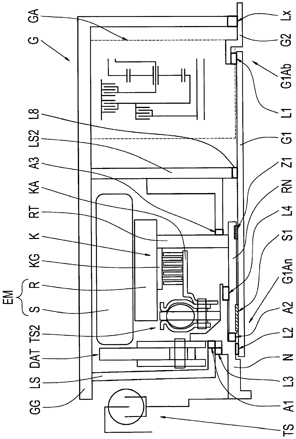
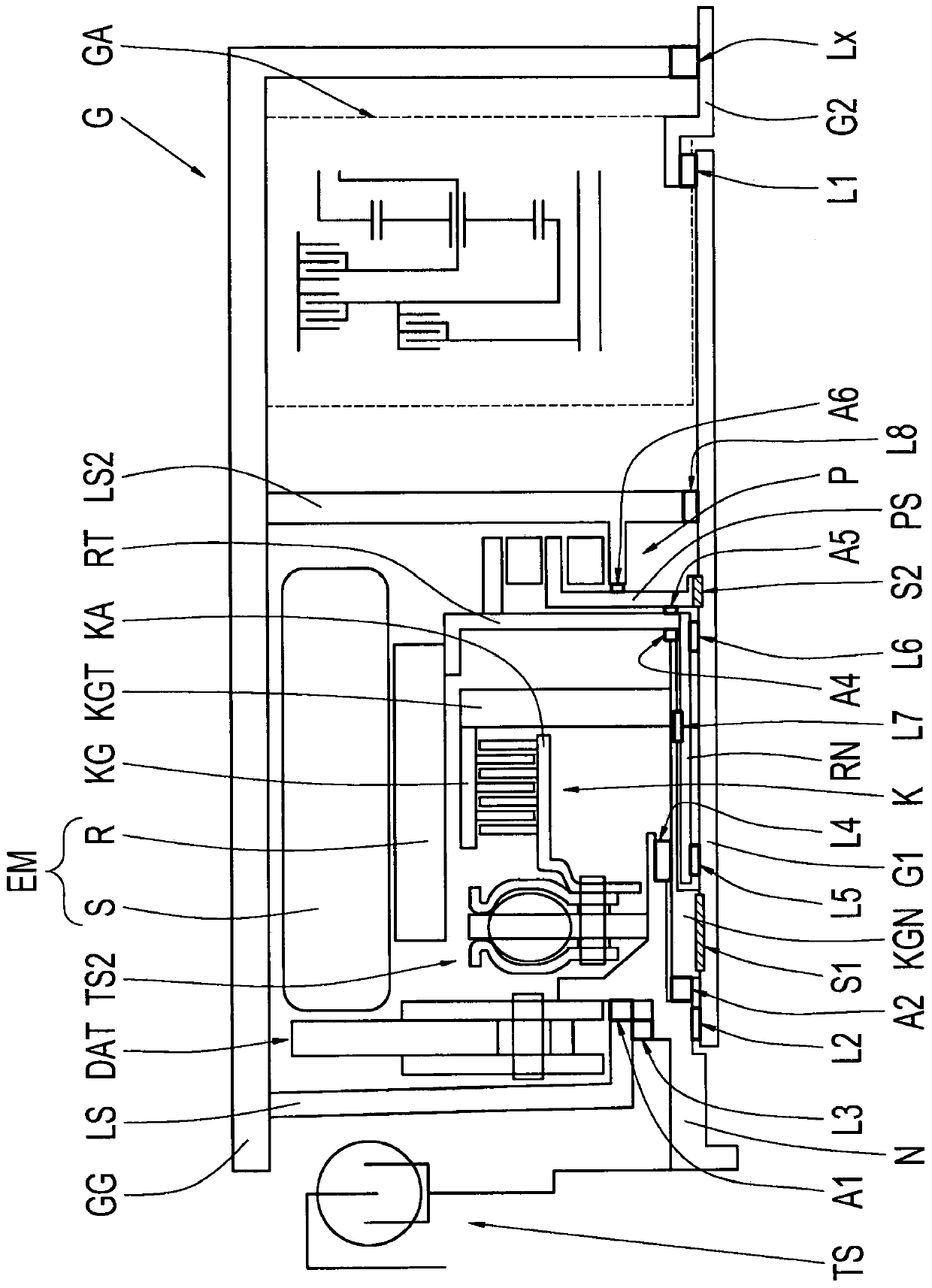
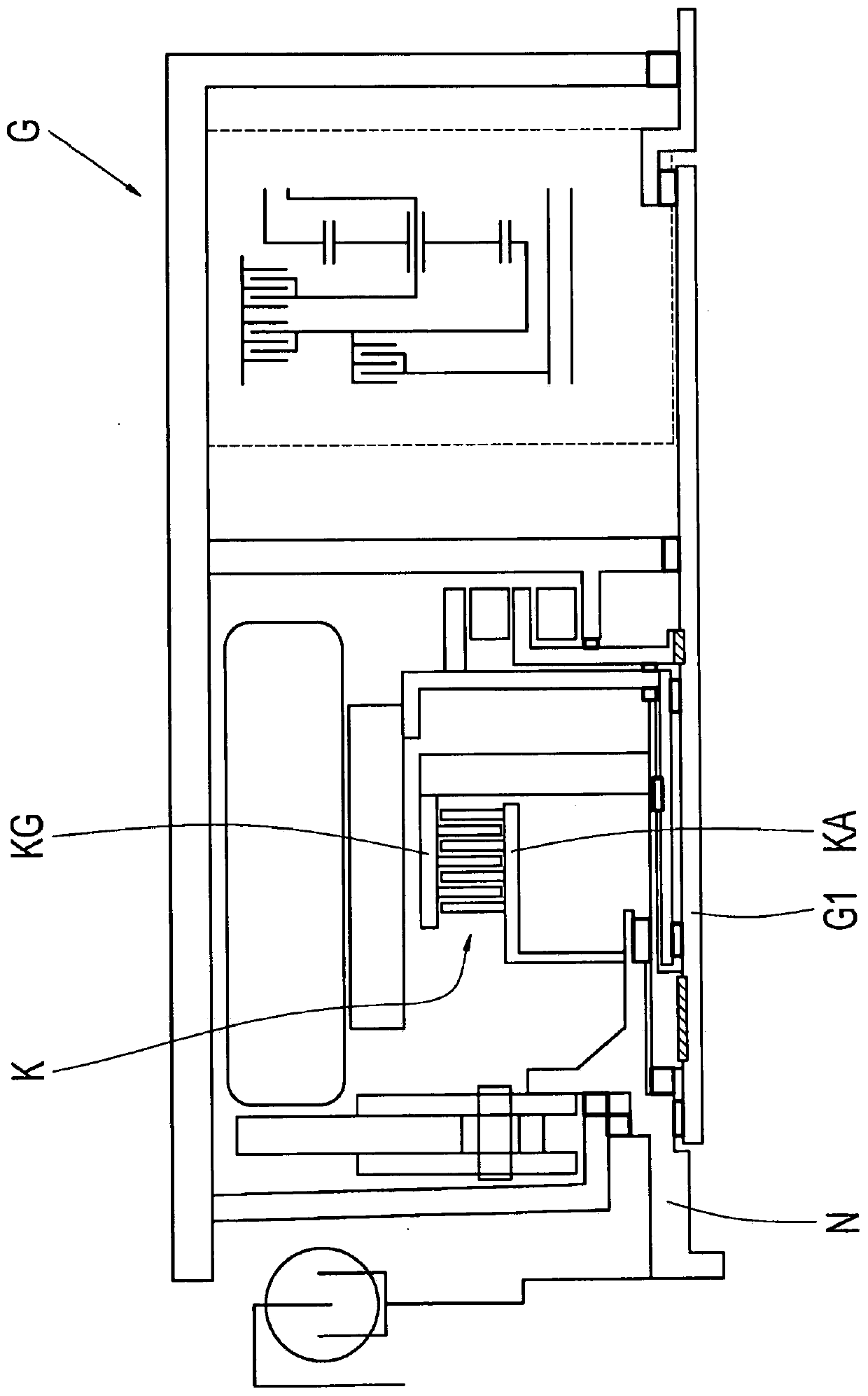
[0026] figure 1 A schematic diagram of a first embodiment of the transmission G is shown. The transmission G has a drive shaft G1, a driven shaft G2 and a gear changing device GA, which is in figure 1 only implied. The gear change device GA is designed to provide different gear ratios between the drive shaft G1 and the output shaft G2 , for example by means of planetary gear sets and shift elements interacting with the planetary gear sets.

[0027] The transmission G also has a housing GG, a hub N, a disconnect clutch K (comprising a first clutch half KA and a second clutch half KG) and an electric machine EM (comprising a rotatable rotor R and a non-rotatable stator relative to the housing GG S). The separating clutch K is designed as a wet-running multi-plate clutch by way of example, with the aid of suitable figure 1 An actuating device not shown in can be actuated, for example by means of a hydraulically actuatable piston. The hub N is connected to the torsional vi...


PUM


Abstract

The invention relates to a transmission (G) for a motor vehicle, said transmission being designed to provide different gear ratios between a drive shaft (G1) and an output shaft (G2) of the transmission (G) by means of a gear changing device (GA). The transmission (G) has a housing (GG), a hub (N) which is connected to a torsional vibration damper (TS), and a separating clutch (K) with a first clutch half (KA) and a second clutch half (KG). The hub (N) is connected to the first clutch half (KA), and the driveshaft (G1) is rotationally fixed to the second clutch half (KG) and protrudes axiallyinto the gear changing device (GA). A first axial end (G1Ab) of the drive shaft (G1) sits directly or indirectly on the housing (GG) in the radial direction via a first bearing (L1), a second axial end (G1An) sits directly on the hub (N) in the radial direction via a second bearing (L2), and the hub (N) sits directly on a bearing shield (LS) which is rotationally fixed to the housing (GG) in the radial direction via a third bearing (L3). The invention also relates to a powertrain for a motor vehicle comprising such a transmission (G).

Description

technical field [0001] The invention relates to a transmission for a motor vehicle, and to a drive train for a motor vehicle, comprising such a transmission. A transmission here refers in particular to a multi-speed transmission in which a plurality of gears, ie fixed transmission ratios between the drive shaft and the output shaft of the transmission, can be shifted preferably automatically via shifting elements. The shifting element is here, for example, a clutch or a brake. Such transmissions are used in particular in motor vehicles in order to suitably adapt the rotational speed and torque output characteristics of the drive unit to the driving resistance of the vehicle. Background technique [0002] The applicant's patent application DE 10 2008 040 498 A1 describes a hybrid drive train of a motor vehicle, in which a hybrid module is connected upstream of an automatic transmission. The hybrid module here has a torsional vibration damper, an electric machine, an input t...

Claims


Application Information

Patent Timeline
Patent Type & Authority Applications(China)
IPC IPC(8): F16H57/021
CPCF16H2057/02034F16H57/021B60K2006/4825B60K6/48F16H2057/0216F16H3/44F16H3/72
Inventor T·里迪塞尔K·菲勒
Owner ZF FRIEDRICHSHAFEN AG
Learn More