
Combined magnetic collector for electromagnetic pulsation welding

An electromagnetic pulse and magnetic collector technology, applied in high frequency current welding equipment, welding equipment, welding equipment and other directions, can solve the problems of prolonged manufacturing cycle, increased processing cost, low utilization rate of magnetic collectors, etc., to improve the utilization rate, avoid The effect of longer working hours

Active Publication Date: 2019-05-28
CHONGQING UNIVERSITY OF SCIENCE AND TECHNOLOGY
View PDF6 Cites 10 Cited by
  • Summary
  • Abstract
  • Description
  • Claims
  • Application Information

AI Technical Summary

Problems solved by technology

It can be seen that in the magnetic pulse forming technology, the application of the magnetic collector is still very simple, and the corresponding magnetic collector needs to be paired with the tubular or plate-shaped workpiece, which requires additional processing of the magnetic collector that conforms to the shape of the workpiece. The utilization rate of magnets is very low, and the processing cost increases, prolonging the manufacturing cycle
When replacing the magnetic collector, it is necessary to rewind the coil outside the magnetic collector, because the manufacturing and winding process of the coil is relatively complicated, so when the magnetic collector is replaced, it is tantamount to increasing the processing cost

Method used


Image

  • Combined magnetic collector for electromagnetic pulsation welding
  • Combined magnetic collector for electromagnetic pulsation welding
  • Combined magnetic collector for electromagnetic pulsation welding

Examples


Embodiment

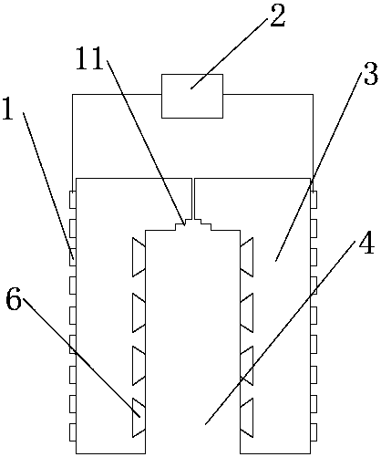
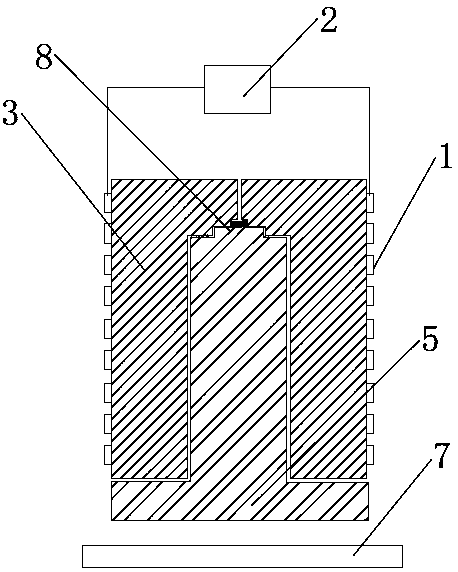
[0021] Such as figure 1 As described above, an asymmetric magnetic concentrator for electromagnetic pulse welding, the magnetic concentrator is externally connected with a general-purpose coil 1, and the coil 1 is connected to the external electromagnetic pulse power supply 2 through a wire, so that when the electromagnetic pulse power supply 2 is discharging, the coil 1 is The change generates an induced magnetic field, and at the same time, an induced current is generated in the magnetic collector inside it, thereby forming an induced magnetic field. In the central welding area, the magnetic field force is the most concentrated, and the electromagnetic force is also the largest because the current density is the largest. The huge electromagnetic force causes metallurgical changes in the welding area, and then realizes the welding of the workpiece.

[0022] Since the shape of the magnetic collector in the prior art needs to match the workpiece to be welded, such as a tube or ...


PUM


Abstract

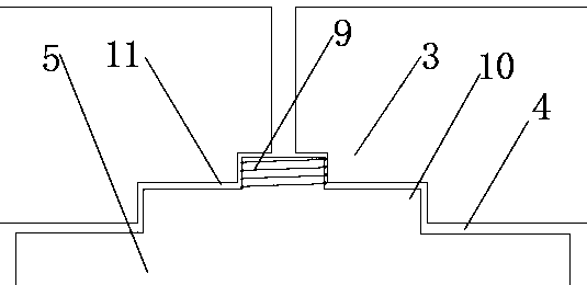
The invention discloses a combined magnetic collector for electromagnetic pulsation welding. The combined magnetic collector comprises a coil, a power supply and a magnetic collector body, wherein thecoil is wound around the outer side of the magnetic collector body, and the coil is connected with the power supply through wires. When tubular workpieces are welded, the magnetic collector body comprises a first component, wherein the outside of the first component is a cylinder, and a central groove is formed in the axial direction of the first component; the cross section of the first component is a U shape, and the coil is uniformly distributed on the outer surface of the first component; and when plate-shaped workpieces are welded, the magnetic collector body further comprises a second component, wherein the second component is of a convex structure matched with a central groove of the first component in use and is provided a T-shaped cross section, and the top end of the convex partof the second component is further provided with a conducting device, so that the first component and the second component are fixed. According to the combined magnetic collector, the method of combining the first component and the second component is adopted, when two workpieces in different shapes are welded, different special magnetic collectors do not need to be replaced, and welding of the tubular workpieces and the plate-shaped workpieces can be realized only by using the first component alone or by combining the first component and the second component.

Description

technical field [0001] The invention relates to the technical field of magnetic collectors for welding, in particular to a combined magnetic collector for electromagnetic pulse welding. Background technique [0002] Magnetic pulse forming technology has the advantages of easy and precise control of processing energy, fast forming speed, high precision of formed workpiece, simple mold and strong versatility of equipment, and the entire forming process is pollution-free. It has been used in many fields such as machinery, electronics, and automobiles. The basic principle of magnetic pulse forming technology is the law of electromagnetic induction. The pulsed magnetic field passes through the workpiece and generates an induced current on the workpiece. The magnetic field generated by the induced current interacts with the initial magnetic field to generate a huge pulsed magnetic pressure. When this pressure amplitude is significantly higher than the yield strength of the workpie...

Claims


Application Information

Patent Timeline
IPC IPC(8): B23K13/01B23K13/00B23K37/00
Inventor 王刚尹立孟张中文姚宗湘张丽萍
Owner CHONGQING UNIVERSITY OF SCIENCE AND TECHNOLOGY
Learn More