Loading device for air duct production line, and air duct production line

A production line and air duct technology, applied in other manufacturing equipment/tools, metal processing, manufacturing tools, etc., can solve problems such as heavy maintenance workload, stacked bending, complex overall structure of equipment, etc., to reduce maintenance workload, The effect of avoiding stacked bending and simplifying the structure

Inactive Publication Date: 2019-05-28
天津赫利通环境科技有限公司
View PDF0 Cites 1 Cited by
  • Summary
  • Abstract
  • Description
  • Claims
  • Application Information

AI Technical Summary

Problems solved by technology

[0003] However, the structure of some feeding devices in the existing automated pipe-dividing production line is too simple and only serves as a simple support for the original coils, and the support radius of the support components cannot be adjusted, so when loading coils with different support inner diameters When supporting, you can only replace the supporting components with the corresponding supporting radius to complete the supporting work. At the same time, the original part of the feeding mechanism lacks self-driven equipment, and the unwinding of the coil needs to be realized by the pulling force of the follow-up equipment, so the unwinding of the coil The material speed cannot be guaranteed, and it is easy to accumulate and bend due to too much material discharge. Some feeding mechanisms are equipped with self-driven equipment on each set of support components, which makes the overall structure of the equipment too complicated, resulting in later maintenance work Larger amount

Method used


Image

  • Loading device for air duct production line, and air duct production line
  • Loading device for air duct production line, and air duct production line
  • Loading device for air duct production line, and air duct production line

Examples


Embodiment Construction

[0028] In order to better understand the present invention, the present invention will be further described below in conjunction with specific embodiments and accompanying drawings.

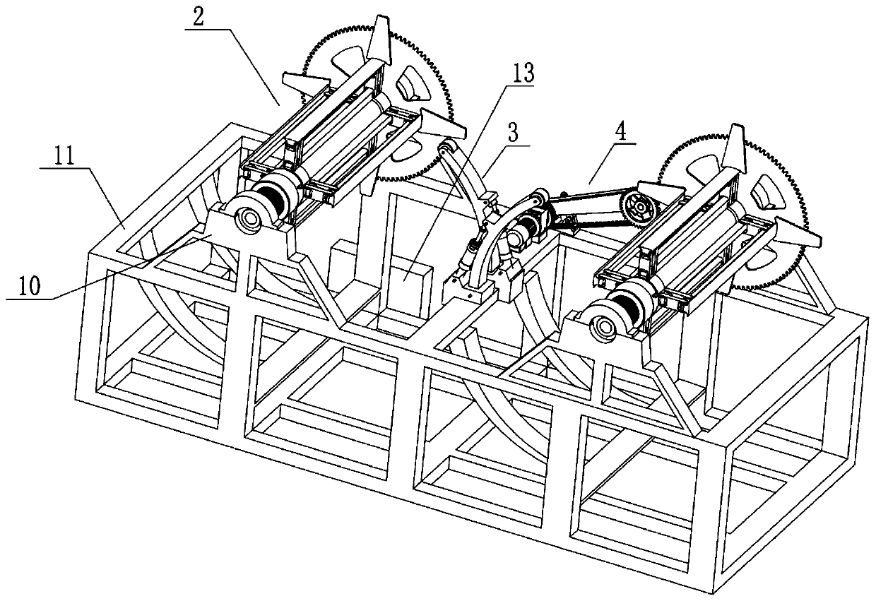
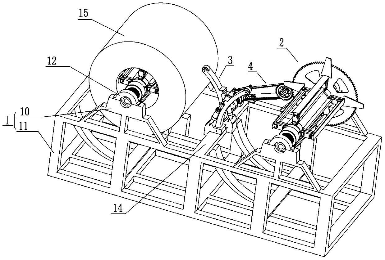
[0029] Such as Figure 1 to Figure 9 As shown, a feeding device for an air duct production line includes a placement frame 1, two sets of material placement mechanisms 2, two sets of pressing mechanisms 3 and a transmission mechanism 4, and the two sets of material placement mechanisms 2 are arranged in parallel with each other at intervals. The group material placement mechanism 2 is all arranged on the top of the placement frame 1 through bearing rotation, and the transmission mechanism 4 is fixedly arranged on the top of the placement frame 1, and the transmission mechanism 4 can be meshed and driven with one of the group of material placement mechanisms 2 as required. The group pressing mechanism 3 is fixed on the top of the placement frame 1 by screws.

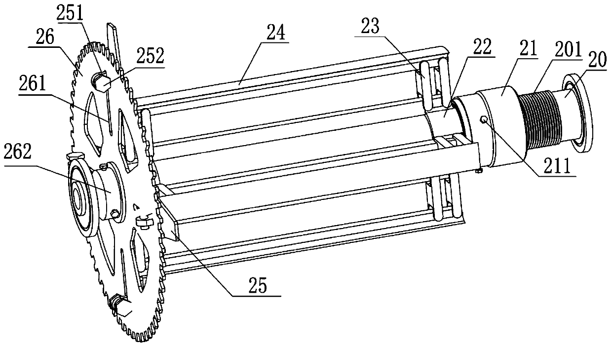
[0030] Placement frame 1 comprises f...


PUM


Abstract

The invention provides a loading device for an air duct production line, and the air duct production line. The loading device for the air duct production line comprises a placement rack, storage mechanisms, compression mechanisms and a transmission mechanism, wherein two groups of the storage mechanisms are mutually arranged at intervals and in parallel, and are rotationally arranged at the top end of the placement rack separately; the transmission mechanism is fixed to the top of the placement rack, and capable of forming engagement transmission with one group of the storage mechanisms separately; and two groups of the compression mechanisms are fixed to the top end of the placement rack. According to the loading device for the air duct production line, and the air duct production line, the storage mechanisms are driven through the transmission mechanism to ensure the controllability of a discharge speed for coiled materials, and stacking and bending caused to the raw materials due toexcessive discharge can be avoided. Moreover, any one group of the storage mechanisms can be driven as needed by a group of motors through the transmission mechanism, the original manner of needing one group of motors to drive each group of the storage mechanisms is replaced, the structure of the device is simplified, and the later-period maintenance workload is reduced. Meanwhile, adjustable support radiuses of the storage mechanisms are achieved through expansion-contraction mechanisms, so that the practicability is improved.

Description

technical field [0001] The invention relates to the field of galvanized air duct production equipment, in particular to a feeding device for an air duct production line and the air duct production line. Background technique [0002] The air duct is generally made of galvanized sheet after a series of processing and finally bent into shape. In daily production and life, the air duct is widely used for the transportation of cold and hot air in the central air conditioner and the external transportation of oily fumes in restaurants. With the development of technology, the current air duct production has basically been replaced by the automatic production line to the original manual production process of the air duct production. [0003] However, the structure of some feeding devices in the existing automated pipe-dividing production line is too simple and only serves as a simple support for the original coils, and the support radius of the support components cannot be adjusted,...

Claims


Application Information

Patent Timeline
IPC IPC(8): B23Q7/00B23P23/04
Inventor 许德凤任怀学
Owner 天津赫利通环境科技有限公司
Why Eureka
Try Eureka