Vehicle, sub-frame mounting structure and design method of sub-frame mounting structure

A technology of installation structure and design method, which is applied in the field of vehicles, can solve the problems of endangering the living space of occupants, increasing cycle and cost, and large vehicle acceleration.

Active Publication Date: 2019-05-28
SAIC MOTOR
View PDF8 Cites 8 Cited by
  • Summary
  • Abstract
  • Description
  • Claims
  • Application Information

AI Technical Summary

Problems solved by technology

For the current front suspension is relatively short, the collision space of the front cabin is limited, and the non-failure design of the sub-frame will inevitably lead to the deformation of the front cabin of the whole vehicle and the performance of rigidity, the acceleration of the whole vehicle is too high, and the occupants will be seriously injured. If the restraint system and the airbag configuration To solve the problem, the design cycle and cost of the vehicle will increase significantly; if the installation point of the subframe is designed to fail, although the dynamic collision space is increased, which is beneficial to the collision, the powertrain will continue to invade the front wall, resulting in excessive deformation of the passenger compartment. Hazard to occupant living space

Method used


Image

  • Vehicle, sub-frame mounting structure and design method of sub-frame mounting structure
  • Vehicle, sub-frame mounting structure and design method of sub-frame mounting structure
  • Vehicle, sub-frame mounting structure and design method of sub-frame mounting structure

Examples


Embodiment Construction

[0032] In order to enable those skilled in the art to better understand the technical solutions of the present invention, the present invention will be further described in detail below in conjunction with the accompanying drawings and specific embodiments.

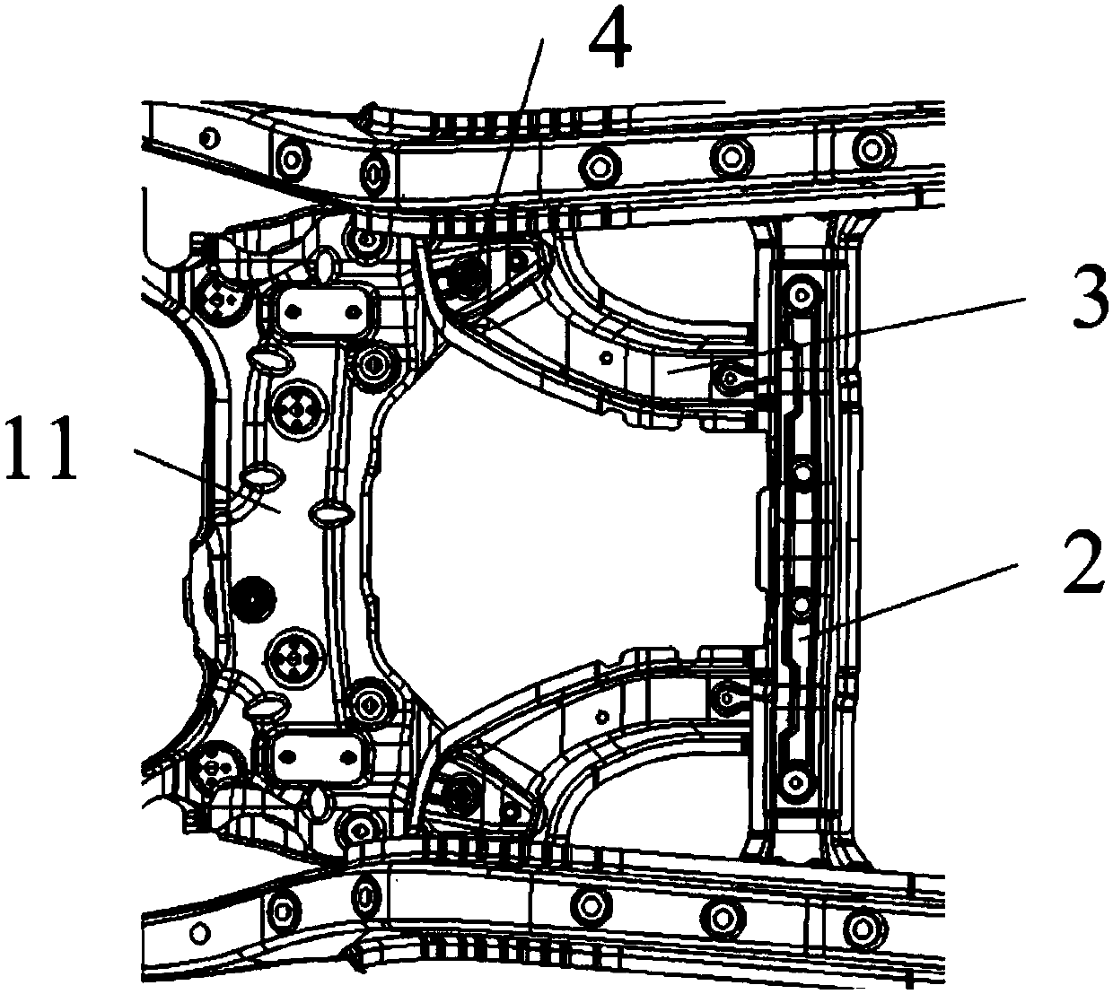
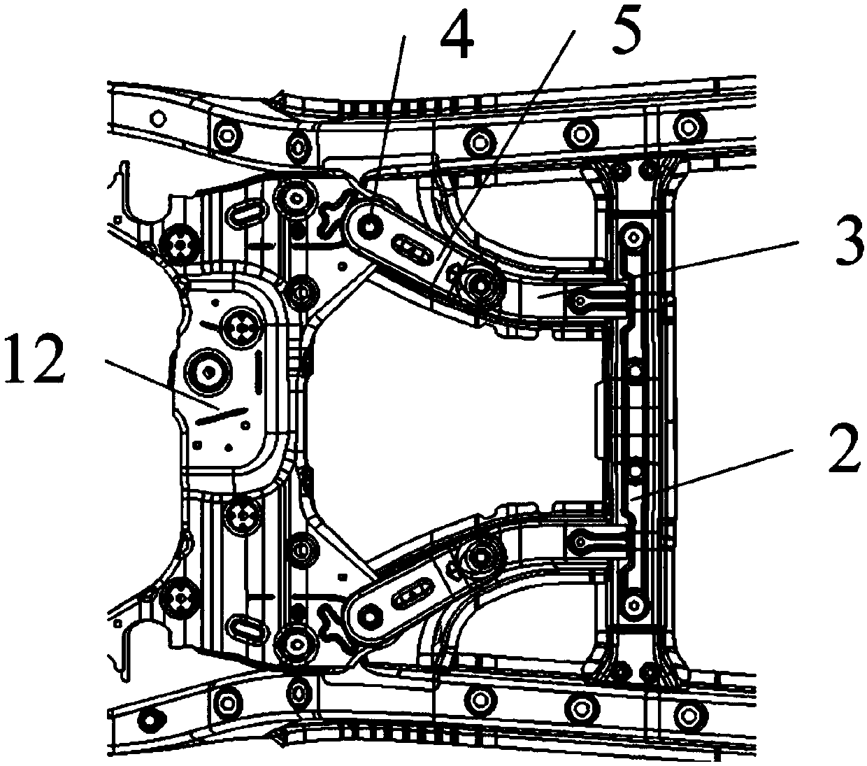
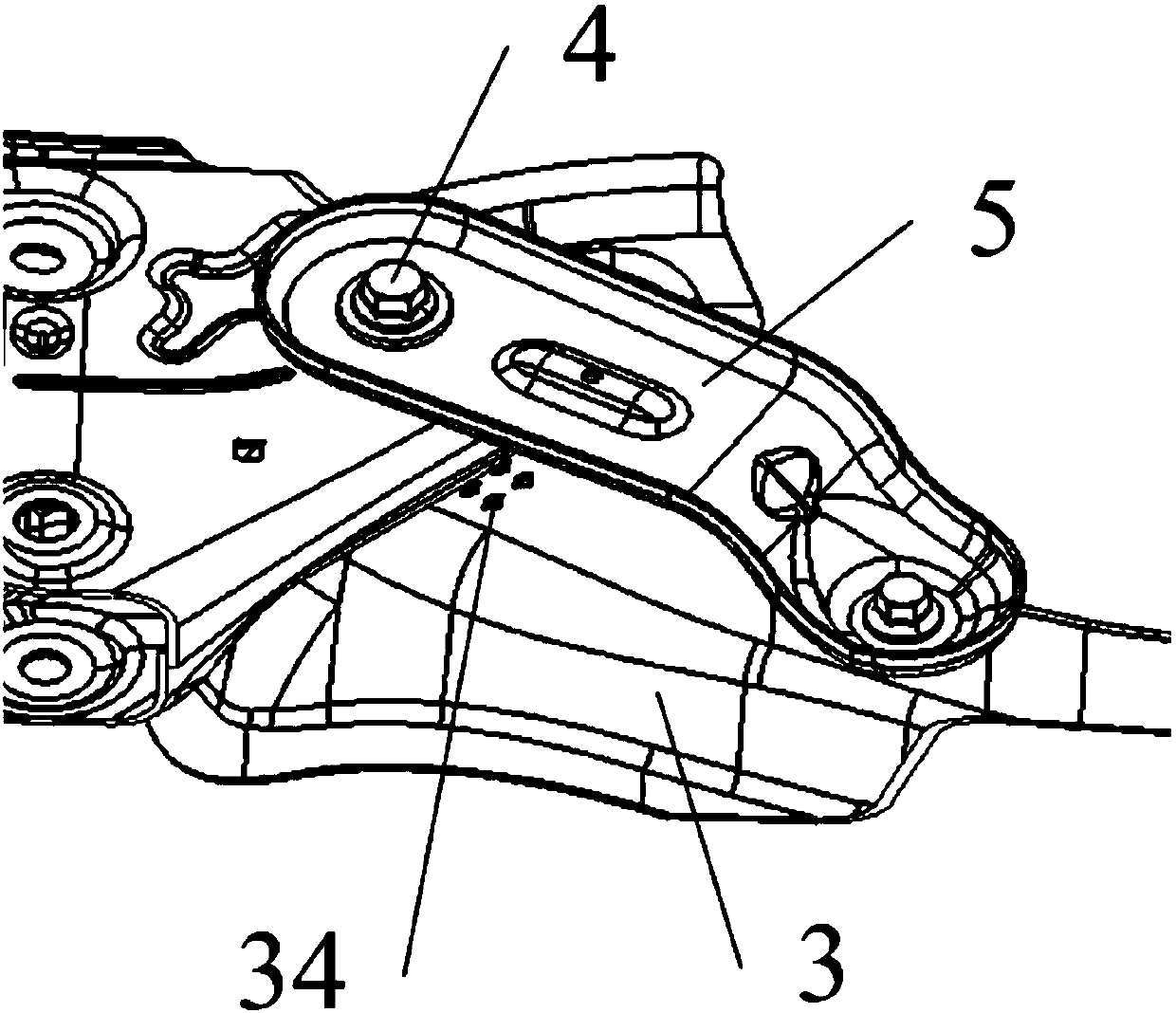
[0033] Please refer to Figure 1-5 , figure 1 It is a top view of the connection structure between the sub-frame and the vehicle body of the embodiment of the present invention; figure 2 Yes figure 1 bottom view of image 3 Yes figure 1 Connection structure diagram of middle and auxiliary frame, liner and body mounting bracket; Figure 4 Yes figure 1 Schematic diagram of the structure of the middle body mounting bracket; Figure 5 It is a comparative diagram of the shear force suffered by the connecting bolts in the collision process between the embodiments of the present invention and the prior art.

[0034] Embodiments of the present invention provide a vehicle, a sub-frame installation structure and a design me...


PUM


Abstract

The invention relates to a vehicle, a sub-frame mounting structure and a design method of the sub-frame mounting structure, wherein the sub-frame mounting structure comprises vehicle body mounting brackets and connecting bolts; the vehicle body mounting brackets are connected between a sub-frame and a floor first cross beam; the connecting bolts are used for connecting the vehicle body mounting brackets with an upper connecting plate and a lower connecting plate of the sub-frame; a reinforcing support is further fixedly arranged on each vehicle body mounting bracket; a notch facing each reinforcing support is formed in each bolt mounting hole; during collision, the connecting bolts squeeze the notches to enable the notches to undergo tear deformation and extend toward the reinforcing supports; and the connecting bolts move with the tear deformation to the reinforcing supports until the connecting bolts break. According to the sub-frame mounting structure, the dynamic collision space ofa whole vehicle can be increased by controlling the deformation of the sub-frame and the vehicle body mounting brackets and the bolt failure under the condition of a certain front suspension size, sothat the carrying capacity of the dynamic collision space is improved, the overall energy absorption efficiency of the vehicle is enhanced, the intrusion of a vehicle powertrain into a front wall isreduced and the direct impact on a passenger compartment is reduced.

Description

technical field [0001] The invention relates to the technical field of vehicles, in particular to a vehicle, an auxiliary frame installation structure and a design method thereof. Background technique [0002] At present, with the vigorous development of the automobile industry, various automobile laws and regulations are becoming more and more perfect, and the requirements for automobile collision safety performance are also getting higher and higher. In fact, the requirements for collision performance to a large extent reflect the requirements for collision space. Whether in traditional vehicles or electric vehicles, the effective collision space between the powertrain and the front wall structure is limited. In most models, The intrusion of the front wall is caused by the impact of the powertrain on the front wall structure, causing deformation of the passenger compartment structure and affecting the safety of the passengers. [0003] In order to improve the safety of th...

Claims


Application Information

Patent Timeline
Patent Type & Authority Applications(China)
IPC IPC(8): B62D21/00
Inventor 陈军李政唐凯马政叶平赵唯戴江璐张阳张平张振富
Owner SAIC MOTOR
Why Eureka
Try Eureka