Flow pass and cavity wall integrated heat absorber with heat storage solar cavity

A technology of solar energy and heat absorbers, which is applied in the field of heat absorbers with heat storage solar cavity, can solve the problems that heat absorbers cannot be designed in an integrated manner, increase complexity and production costs, and achieve simple structure, convenient operation, light -Effect of high heat conversion efficiency

Pending Publication Date: 2019-05-28
HUNAN UNIV OF SCI & TECH
View PDF0 Cites 3 Cited by
  • Summary
  • Abstract
  • Description
  • Claims
  • Application Information

AI Technical Summary

Problems solved by technology

On the other hand, the metal coil heat absorber cannot be directly integrated with the heat storage medium, and

Method used


Image

  • Flow pass and cavity wall integrated heat absorber with heat storage solar cavity
  • Flow pass and cavity wall integrated heat absorber with heat storage solar cavity
  • Flow pass and cavity wall integrated heat absorber with heat storage solar cavity

Examples


Embodiment 1

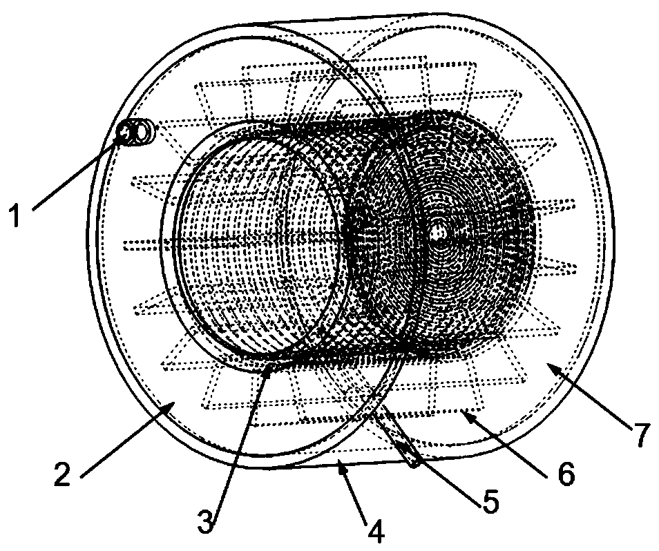
[0028] Such as figure 1 As shown, the present invention includes a front sealing plate 2 , a heat absorbing body 3 , a peripheral plate 4 , a working fluid inflow pipe 5 , a heat exchange fin 6 , a rear sealing plate 7 , a spiral channel hole 8 , and a working medium outflow pipe 9 . The heat absorber 3 is a cylindrical cavity structure with an opening at one end, and one end of the opening is used to receive solar light energy gathered by a solar concentrator, and a quartz glass plate is provided at the opening to reduce the heat absorber. 3 Radiative and convective heat loss. The inner surface of the heat absorber 3 is coated with a high-temperature-resistant coating that can efficiently absorb solar energy, and the outer side of the bottom plate is wrapped with an insulating material for reducing radiation and convective heat loss of the heat absorber 3 .

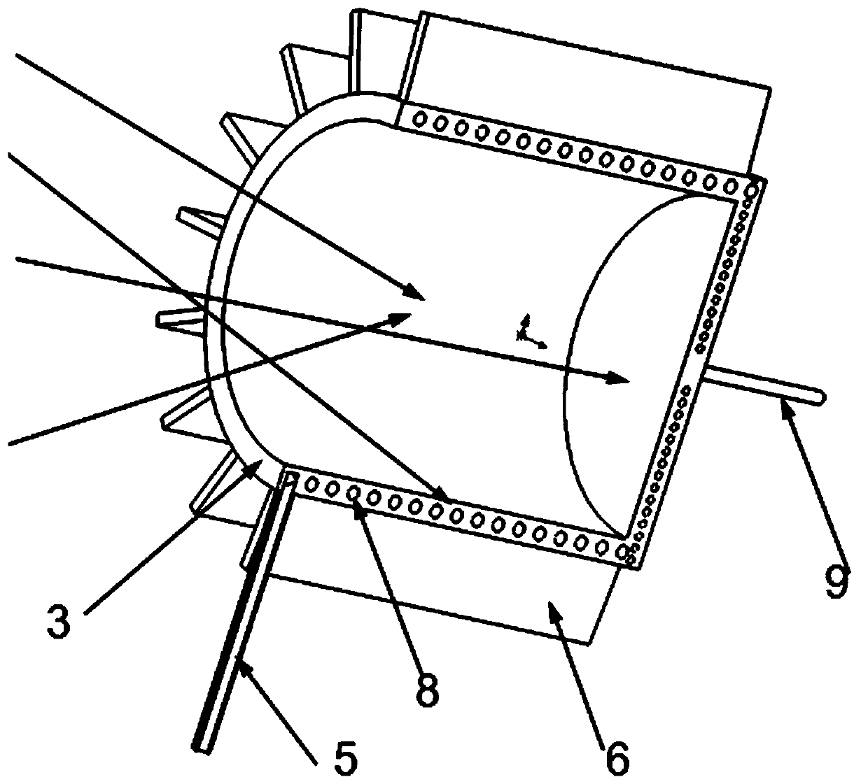
[0029] Such as figure 2 As shown, the side wall of the heat absorber 3 is provided with a spiral spiral channel hol...

Embodiment 2

[0033] Such as Figure 4 As shown, the structure is similar to that of Embodiment 1, and its difference from Embodiment 1 lies in the structure of the heat absorber 3 . In this embodiment, the heat absorber 3 is composed of a tubular body 12 , a front cover 10 and a rear cover 11 , and is a cylindrical cavity structure with one end open.

[0034] The side wall of the tubular body 12 is provided with a plurality of vertical flow channel holes 13, and the plurality of vertical flow channel holes 13 are evenly distributed along the circumferential direction. The cross-sectional geometry of the vertical flow channel holes 13 can be circular, oval, rectangular and triangles etc.

[0035] The front end of the tubular body 12 is provided with a front cover 10 , and the rear end is provided with a rear cover 11 . The front cover 10 is an annular structure whose inner hole radius is less than or equal to the inner hole radius of the tubular body 12. The front cover 10 is provided with ...


PUM


Abstract

The invention discloses a flow pass and cavity wall integrated heat absorber with a heat storage solar cavity. The heat absorber comprises a heat absorbing body, a working medium inflow pipe and a working fluid outflow pipe. The heat absorbing body is of a cylindrical cavity structure with one end opened, the opened end is used for receiving solar energy concentrated from a solar concentrator, a working medium flow pass is arranged in the side wall of the heat absorbing body, one end of the working medium flow pass communicates with the working medium inflow pipe, the other end of the workingmedium flow pass communicates with the working medium outflow pipe, the working medium inflow pipe and the working medium outflow pipe are installed on the heat absorbing body, and an annular cavity space is arranged on the outer side o the heat absorbing body and filled with phase change heat storage media. The sunlight absorbing function and the worming medium heating function of the wall face of a cavity are integrated, the annular cavity is filled with the phase change heat storage materials, heat energy storage is achieved, and the heat absorber further has the advantages of being simplein structure, convenient to operate, high in light-heat conversion efficiency, safe and reliable.

Description

technical field [0001] The invention relates to the field of solar energy concentrating heat collection and utilization, in particular to a solar cavity heat absorber with heat storage integrated with a flow channel and a cavity wall. Background technique [0002] Concentrating solar thermal power generation technology gathers sunlight energy into the cavity heat absorber through a large-area concentrator and heats the internal fluid working medium, and then drives the generator set to generate electricity through the thermodynamic cycle process, which is an important aspect of solar thermal utilization. It is also considered to be an important way to develop and utilize clean and environmentally friendly solar energy resources to solve energy shortages and environmental pollution. [0003] The heat absorber is the core device of light-to-heat energy conversion in the solar thermal power generation system, and it uses the high-density sunlight energy it receives to heat the ...

Claims


Application Information

Patent Timeline
IPC IPC(8): F24S60/00F24S10/70F24S80/00F24S23/00
CPCY02E10/44
Inventor 颜健彭佑多叶笑洋刘永祥
Owner HUNAN UNIV OF SCI & TECH
Why Eureka
Try Eureka