
System and method for calibrating multiple high-voltage current transformers

A high-voltage current and transformer technology, applied in the field of electric power, can solve the problems of increasing wiring errors, time-consuming, and short supply of the verification quantity of the verification station, and achieve the effect of improving the wiring efficiency, improving the verification ability, and shortening the verification time.

Inactive Publication Date: 2019-05-28
GUIGANG POWER SUPPLY BUREAU OF GUANGXI POWER GRID CO LTD
View PDF14 Cites 0 Cited by
  • Summary
  • Abstract
  • Description
  • Claims
  • Application Information

AI Technical Summary

Problems solved by technology

[0002] With the development of the economy, the demand for high-voltage current transformers is increasing day by day. According to the technical specifications of Guangxi transformers, high-voltage current transformers must use double windings. The conditions of only wiring and single verification, and for double-winding high-voltage current transformers must be verified by winding wiring. When verifying one of the windings, the other winding must be short-circuited. After the verification is completed, replace the other winding. Verification takes a long time And the process is cumbersome, resulting in the situation that the testing quantity of the testing institute is often in short supply, so how to improve the testing ability of the transformer has become an urgent problem to be solved
According to statistics, it takes 25 minutes for a double-winding high-voltage current transformer from wiring to verification, and in this process, there will be increased risk of open circuit due to wrong wiring and poor contact of the secondary circuit of the current.

Method used


Image

  • System and method for calibrating multiple high-voltage current transformers

Examples


Embodiment Construction

[0028] The following will clearly and completely describe the technical solutions in the embodiments of the present invention with reference to the accompanying drawings in the embodiments of the present invention. Obviously, the described embodiments are only some, not all, embodiments of the present invention. Based on the embodiments of the present invention, all other embodiments obtained by persons of ordinary skill in the art without making creative efforts belong to the protection scope of the present invention.

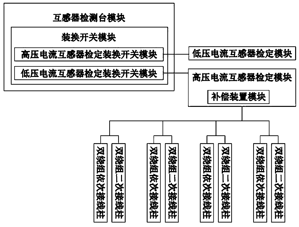
[0029] see figure 1 , the present invention provides a technical solution: a verification system for multiple high-voltage current transformers, including a transformer detection station module, a low-voltage current transformer verification module, and a high-voltage current transformer verification module. The low-voltage current transformer verification module is used for The low-voltage current transformer is verified, and the original verification method ...


PUM


Abstract

The invention discloses a system for calibrating multiple high-voltage current transformers, which comprises a transformer detection table module, a low-voltage current transformer calibration moduleand a high-voltage current transformer calibration module and is characterized in that the transformer detection table module comprises a transformer detection table body; a compensation device moduleis arranged in the high-voltage current transformer calibration module; and four groups of double-winding secondary binding posts and four groups of single-winding secondary binding posts are connected to the high-voltage current transformer calibration module. On the basis of a previous transformer detection platform, modification design is carried out, the previous single wiring mode is changed, the secondary binding posts and primary binding posts of the four groups of double windings are additionally arranged on the lower side surface plate of the high-voltage current transformer calibration module, four high-voltage current transformers of double windings are connected, an existing detection system is optimized, the four high-voltage current transformers of double windings can be automatically detected in sequence, and secondary wires do not need to be disassembled and assembled repeatedly.

Description

technical field [0001] The invention relates to the field of electric power technology, in particular to a verification system and method for multiple high-voltage current transformers. Background technique [0002] With the development of the economy, the demand for high-voltage current transformers is increasing day by day. According to the technical specifications of Guangxi transformers, high-voltage current transformers must use double windings. The conditions of only wiring and single verification, and for double-winding high-voltage current transformers must be verified by winding wiring. When verifying one of the windings, the other winding must be short-circuited. After the verification is completed, replace the other winding. Verification takes a long time And the process is cumbersome, resulting in the situation that the testing quantity of the testing institute is often in short supply, so how to improve the testing ability of the transformer has become an urgent...

Claims


Application Information

Patent Timeline
IPC IPC(8): G01R35/02
Inventor 黄慧君余弦左伟军陈智容
Owner GUIGANG POWER SUPPLY BUREAU OF GUANGXI POWER GRID CO LTD
Learn More