Scene map generation method, device and equipment based on depth camera

A technology of map generation and depth camera, applied in the field of visual robots, can solve the problem of high deployment cost of robot navigation, achieve the effect of reducing deployment cost and requirements

Pending Publication Date: 2019-05-28
UBTECH ROBOTICS CORP LTD
View PDF4 Cites 30 Cited by
  • Summary
  • Abstract
  • Description
  • Claims
  • Application Information

AI Technical Summary

Problems solved by technology

[0004] In view of this, the embodiment of the present invention provides a scene map generation method, device and equipment based on a depth camera to solve the problem of high requirements on hardware e

Method used


Image

  • Scene map generation method, device and equipment based on depth camera
  • Scene map generation method, device and equipment based on depth camera
  • Scene map generation method, device and equipment based on depth camera

Examples


Embodiment Construction

[0044] In the following description, specific details such as specific system structures and technologies are presented for the purpose of illustration rather than limitation, so as to thoroughly understand the embodiments of the present invention. It will be apparent, however, to one skilled in the art that the invention may be practiced in other embodiments without these specific details. In other instances, detailed descriptions of well-known systems, devices, circuits, and methods are omitted so as not to obscure the description of the present invention with unnecessary detail.

[0045] In order to illustrate the technical solutions of the present invention, specific examples are used below to illustrate.

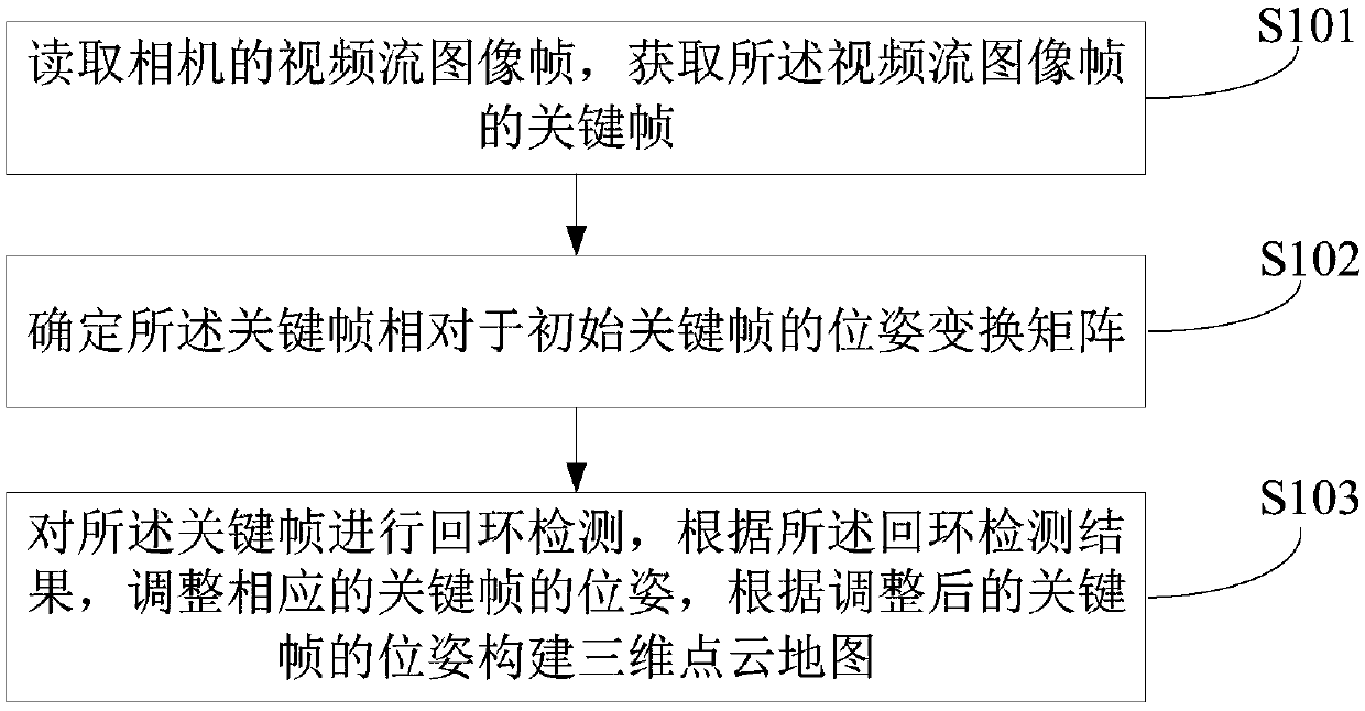
[0046] Such as figure 1 Shown is the implementation process of a method for generating a scene map based on a depth camera provided by the embodiment of the present application, and is described in detail as follows:

[0047] In step S101, a video stream image frame o...


PUM


Abstract

The scene map generation method based on the depth camera comprises the following steps: reading a video stream image frame of the camera; obtaining a key frame of the video stream image frame, determining a pose transformation matrix of the key frame relative to an initial key frame, carrying out loopback detection on the key frame, adjusting the pose of the corresponding key frame according to aloopback detection result, and constructing a three-dimensional point cloud map according to the adjusted pose of the key frame. According to the method, only a small number of effective key frames need to be collected, the requirement for equipment hardware can be greatly reduced, the three-dimensional point cloud map is constructed in a loopback detection mode, and the deployment cost of a navigation scheme on the robot can be remarkably reduced on the premise that the positioning and navigation requirements in a three-dimensional space are met.

Description

technical field [0001] The invention belongs to the field of visual robots, and in particular relates to a method, device and equipment for generating a scene map based on a depth camera. Background technique [0002] Autonomous mobile robot navigation technology is an important research direction in the field of intelligent robots, and the visual navigation method has the advantages of large amount of information, high flexibility, and low cost. Simultaneous positioning and mapping technology of robot vision is a key basic technology of mobile robots, flying robots and other robotic systems, and has indispensable characteristics. [0003] The traditional two-dimensional laser SLAM (Simultaneous Localization and Mapping in English, and Simultaneous Localization and Mapping in Chinese) technology enables the robot to construct a map while positioning in an unknown environment, and then use this map as the basis for path planning. and navigation. The price of 3D lidar can re...

Claims


Application Information

Patent Timeline
IPC IPC(8): G06T17/00G09B29/00
Inventor 熊友军毕占甲刘志超白龙彪
Owner UBTECH ROBOTICS CORP LTD
Why Eureka
Try Eureka