
A split type resonator with different impedance ratios

A split-type resonator and resonator technology, applied in the field of resonators, can solve problems such as not being able to meet the requirements of power capacity, and achieve the effects of increasing the perimeter-area ratio, suppressing high-order harmonics, and improving heat dissipation performance

Pending Publication Date: 2019-05-28
TIANJIN UNIV +1
View PDF6 Cites 2 Cited by
  • Summary
  • Abstract
  • Description
  • Claims
  • Application Information

AI Technical Summary

Problems solved by technology

However, simply relying on the method of increasing the area can no longer meet the requirements of the current resonator for power capacity, and further improvement of the traditional structure is needed.

Method used


Image

  • A split type resonator with different impedance ratios
  • A split type resonator with different impedance ratios
  • A split type resonator with different impedance ratios

Examples


Embodiment Construction

[0032] The following are preferred embodiments of the present invention, but the protection scope of the present invention is not limited thereby.

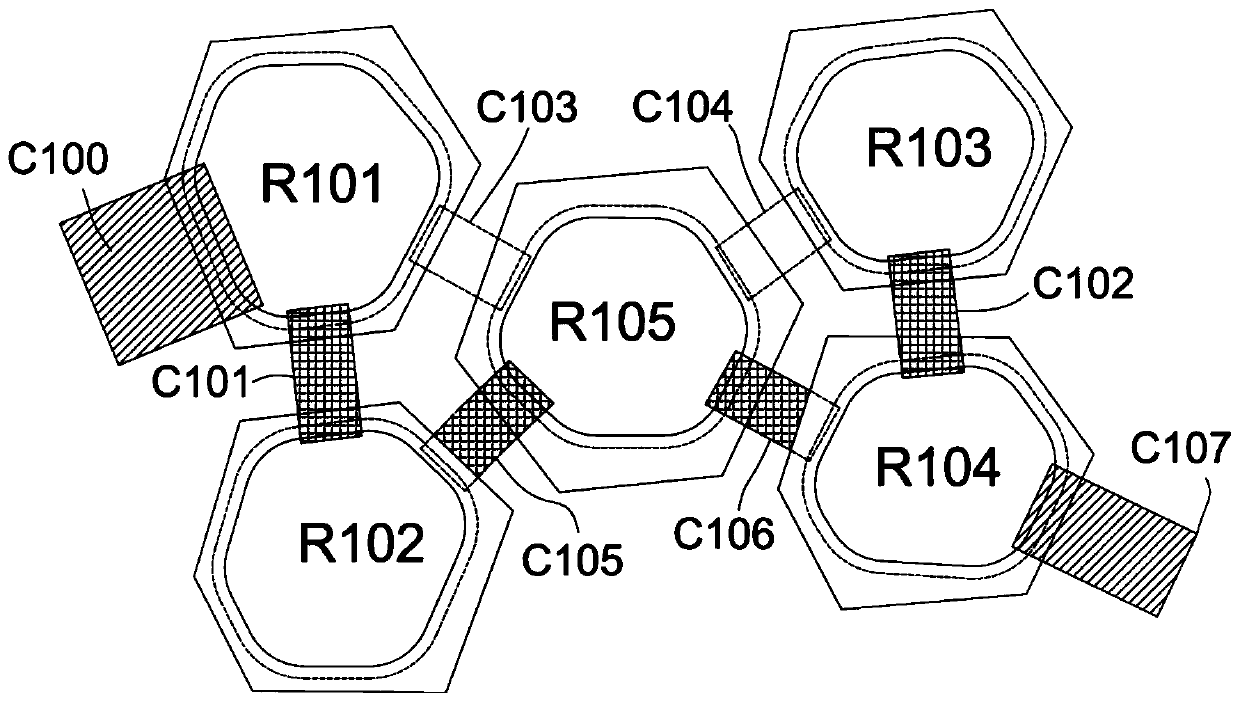
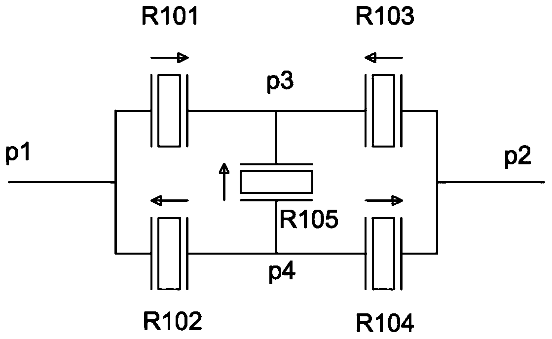
[0033] Figure 1A is a schematic diagram of the structure of the first split resonator according to an embodiment of the present invention. Such as Figure 1A As shown, in the embodiment of the present invention, the traditional single resonator is split into five sub-resonators, and the five sub-resonators are the first resonator R101, the second resonator R102, the third resonator R103, The fourth resonator R104 and the fifth resonator R105.

[0034] Figure 1A The specific connection mode of the 5 resonators is given, which will be described in detail below.

[0035] The upper electrode of the first resonator R101 has a pin C100, and the upper electrode of the first resonator R101 is electrically connected to the upper electrode of the second resonator R102 C101; the lower electrode of the first resonator R101 is connected to ...


PUM


Abstract

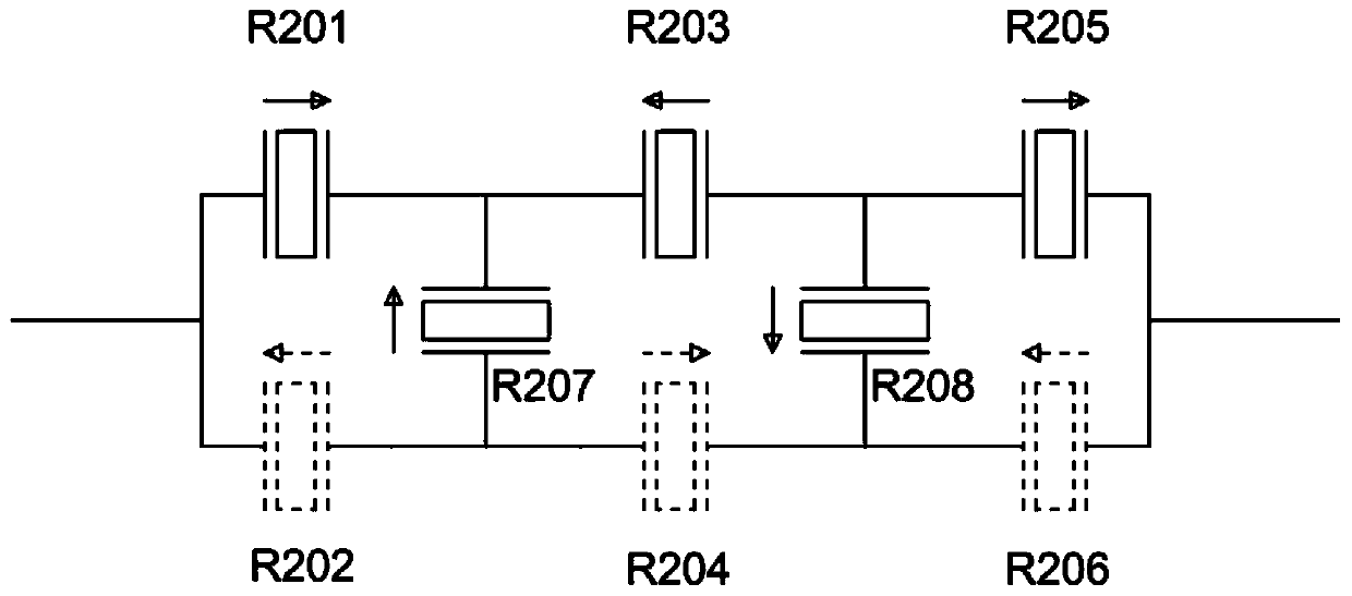
The invention discloses a split-type resonator. The split-type resonator is a resonator group composed of a plurality of sub-resonators. the resonator group comprises more than two parallel branches,and each parallel branch comprises more than two sub resonators which are connected in series; And a bridged single sub-resonator or a bridged sub-resonator group is arranged between the series connection points in the adjacent parallel branches.

Description

technical field [0001] The invention relates to a resonator, in particular to a split resonator with different impedance ratios. Background technique [0002] Thin film bulk wave resonators made of piezoelectric thin films with longitudinal resonance in the thickness direction have become a viable alternative to surface acoustic wave devices and quartz crystal resonators in mobile phone communications and high-speed serial data applications. The RF front-end bulk wave filter / duplexer provides superior filtering characteristics such as low insertion loss, steep transition band, and strong anti-electrostatic discharge (ESD) capability. With the continuous improvement of power capacity requirements for electronic devices such as filters and resonators in the field of communication, the heat generation of filters and resonators has increased significantly. The high temperature caused by high heat generation will cause the Q value of the device and the electromechanical coupling...

Claims


Application Information

Patent Timeline
IPC IPC(8): H03H9/17H03H9/02
Inventor 张孟伦庞慰孙晨
Owner TIANJIN UNIV
Learn More