
System and detection method for transmitting and receiving large depth MRS (Magnetic Resource Sounding)

A technology of transmitting and receiving with a large depth, which is applied in the direction of electron magnetic resonance/nuclear magnetic resonance detection, etc., can solve the problems of damage to receiving instruments and failure to improve efficiency, so as to prevent damage to detection personnel and instruments, expand detection depth, and increase The effect of equivalent area

Pending Publication Date: 2019-03-29
JILIN UNIV
View PDF8 Cites 2 Cited by
  • Summary
  • Abstract
  • Description
  • Claims
  • Application Information

AI Technical Summary

Problems solved by technology

However, due to the limitations of the emission current and emission voltage of the nuclear magnetic resonance detection system, the detection depth of nuclear magnetic resonance has certain limitations. Generally, the diameter of the transmission coil is approximately equal to the underground depth that can be detected, so to increase the detection depth, the emission must be increased. The area of ​​the coil. When the area of ​​the transmitting coil increases, the load impedance of the transmitting coil will increase. When transmitting the same size of transmitting current, a larger transmitting voltage is required. However, due to the limitation of the rated voltage value of the energy storage capacitor, the transmitting The maximum value of the voltage, which limits the depth of MRI detection
[0003] Patent CN106886052A discloses "a high-power nuclear magnetic resonance water detection device and its field use method", which proposes a high-power nuclear magnetic resonance water detection device and its field use method, which is based on cascade emission and parallel charging of multiple storage capacitor banks The method realizes the high-power emission and high-efficiency work of the magnetic resonance water detection device, but the invention uses three sets of energy storage capacitors in parallel to only increase the emission voltage by 1.73 times and the emission depth by 1.75 times, but not 3 times. In addition, the invention greatly improves the emission voltage and emission current, which will induce a larger induced electromotive force in the receiving coil and cause great damage to the receiving instrument.

Method used


Image

  • System and detection method for transmitting and receiving large depth MRS (Magnetic Resource Sounding)
  • System and detection method for transmitting and receiving large depth MRS (Magnetic Resource Sounding)
  • System and detection method for transmitting and receiving large depth MRS (Magnetic Resource Sounding)

Examples


Embodiment 1

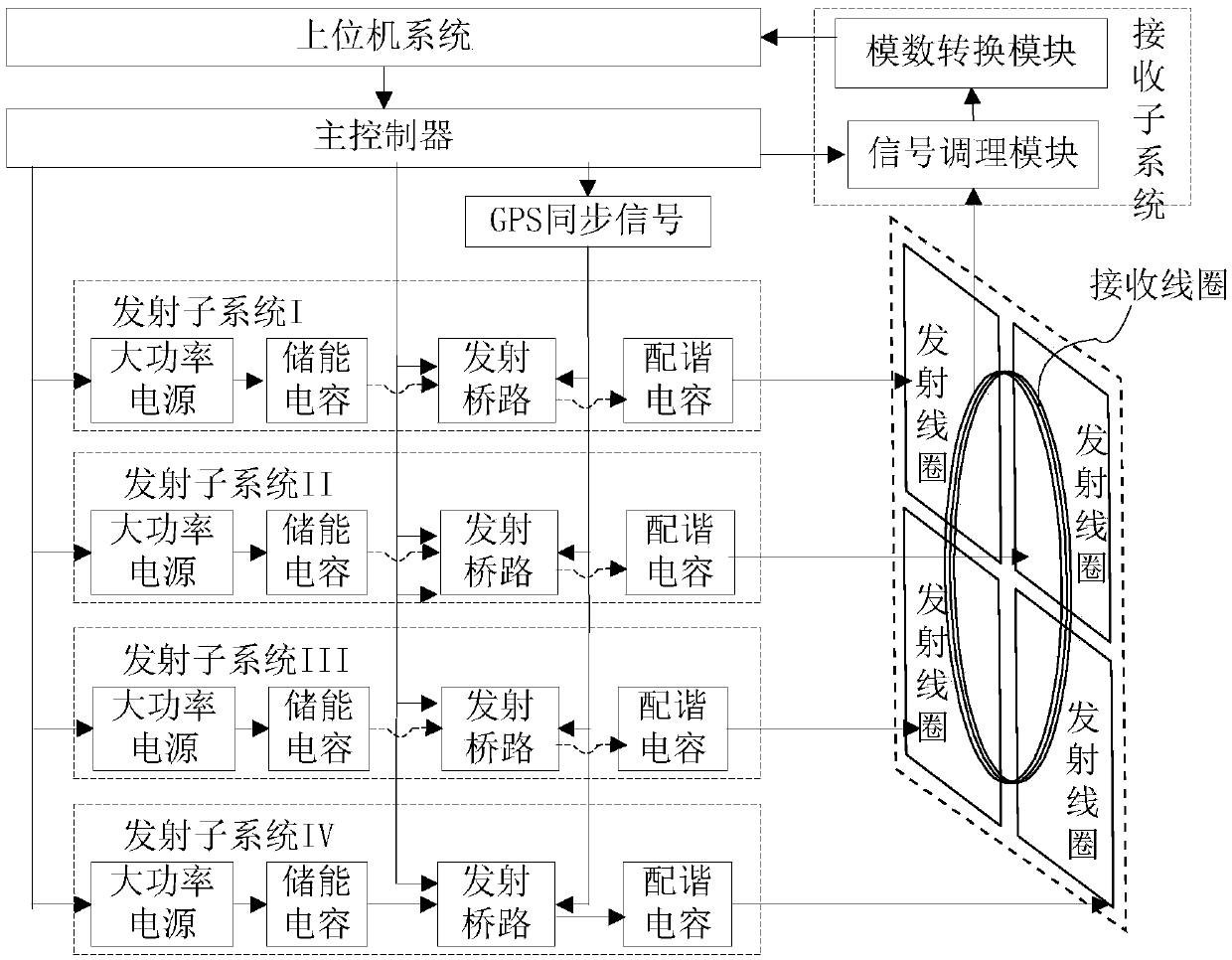
[0058] like figure 1 , a large-depth MRS transmitting and receiving system, including the host computer system connected to the main controller and the analog-to-digital conversion module in the receiving subsystem, the main controller connected to the GPS synchronization signal and four groups of transmitting subsystems: respectively: transmitting subsystem I , transmitting subsystem II, transmitting subsystem III, high-power power supply module and transmitting bridge module in transmitting subsystem IV, and GPS synchronization signals are respectively connected to four groups of transmitting subsystems: transmitting subsystem I, transmitting subsystem II, transmitting sub-system System III, the transmitting bridge module in the transmitting subsystem IV, four sets of transmitting subsystems: transmitting subsystem I, transmitting subsystem II, the composition is the same, respectively connected by high-power power supply to the energy storage capacitor connected to the trans...

Embodiment 2

[0063] The difference from Embodiment 1 is that there are 8 transmitting coils, and one receiving coil is configured for every four transmitting coils. Transmitting coils, if there are 2 receiving coils, the signal conditioning module includes a corresponding number of receiving channels, the transmitting coils can transmit currents of the same size and in the same direction at the same time, and the receiving coils can receive at the same time, or a part of the receiving coils can cover the transmission The coil is not working, the receiving coil acts as a reference coil for the other coils. This facilitates subsequent data analysis.

Embodiment 3

[0065] A large-depth MRS transmitting and receiving detection method for four transmitting coils in this embodiment includes:

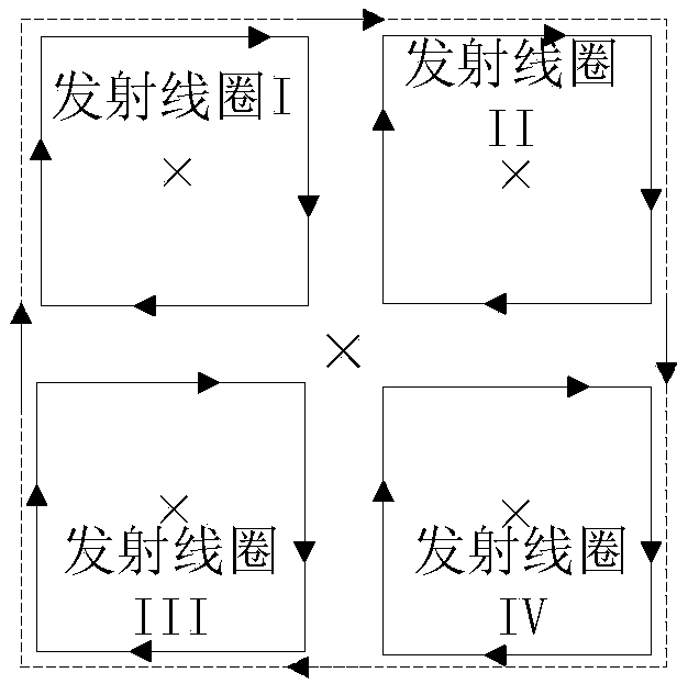
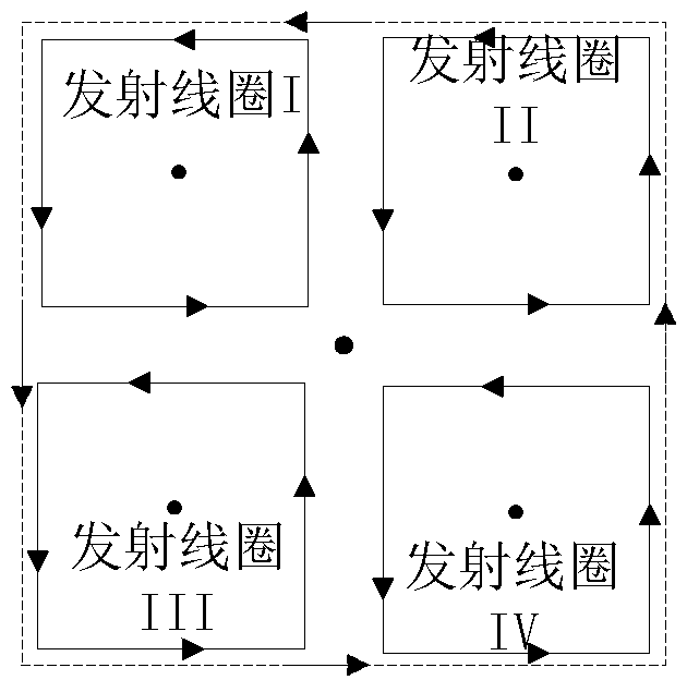
[0066] 1. First, lay out 4 sets of transmitting coils according to the terrain that needs to be detected: transmitting coil 1, transmitting coil 2, transmitting coil 3, and transmitting coil 4, so that the four sets of transmitting coils are placed clockwise to construct a side length that is a single transmitting coil side length 2 times as large a square area as Figure 4 shown;

[0067] 2 Connect 4 sets of transmitting subsystems: transmitting subsystem I, transmitting subsystem II, transmitting subsystem III, and transmitting subsystem IV to 4 sets of transmitting coils: transmitting coil I, transmitting coil II, transmitting coil III, and transmitting coil IV it is good;

[0068] 3 Connect the multi-turn receiving coil with the receiving system, connect the main control system with the transmitting subsystem and the receiving subsystem, and tur...


PUM


Abstract

The invention relates to the field of geophysical exploration, and specifically relates to a system and a detection method for transmitting and receiving a large depth MRS. The system comprises a upper computer system, a main controller, a plurality of transmission subsystems, a plurality of transmission coils corresponding to the number of the plurality of transmission subsystems, a receiving subsystem, and a receiving coil. The plurality of transmission subsystems comprises a high-power output power supply, an energy storage capacitor, a transmission bridge circuit, and a tuning capacitor, wherein the receiving coils are more than one, can work simultaneously, and can also serve as reference coils for other coils. According to the system and the detection method for transmitting and receiving the large depth MRS, the transmission depth is improved, and the subsequent data analysis is facilitated.

Description

technical field [0001] The invention relates to the field of geophysical detection, specifically a large-depth MRS transmitting and receiving system and a detection method. Background technique [0002] Water resources are an important resource to maintain the survival of human society. With the development of science and technology and the rapid growth of population, the shortage of water resources is a difficult problem faced by countries all over the world. Since our country is a country with a large population, the problem of water shortage is particularly serious. At the same time, the water resources in some tunnels and mines will cause some disasters and water accidents, which will have a negative impact on human life and threaten construction workers. Therefore, how to detect water resources accurately, safely and without damage is of great significance. At present, the magnetic resonance detection technology (Magnetic Resource Sounding, MRS) is the only non-destruc...

Claims


Application Information

Patent Timeline
Patent Type & Authority Applications(China)
IPC IPC(8): G01V3/14
CPCG01V3/14
Inventor 刘婷婷尚新磊赵义平刘宇侯佳伟
Owner JILIN UNIV
Learn More