Multi-cavity central venous catheter
A central venous catheter and catheter technology, applied in the direction of catheters, etc., can solve the problems of patients suffering from central venous catheter fixation and easy blockage of central venous catheters, and achieve the effect of changing the way of needle and thread suture fixation, solving pain and reducing workload.
- Summary
- Abstract
- Description
- Claims
- Application Information
AI Technical Summary
Problems solved by technology
Method used
Image

Examples
Embodiment 1
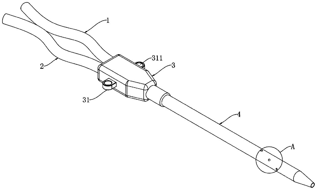
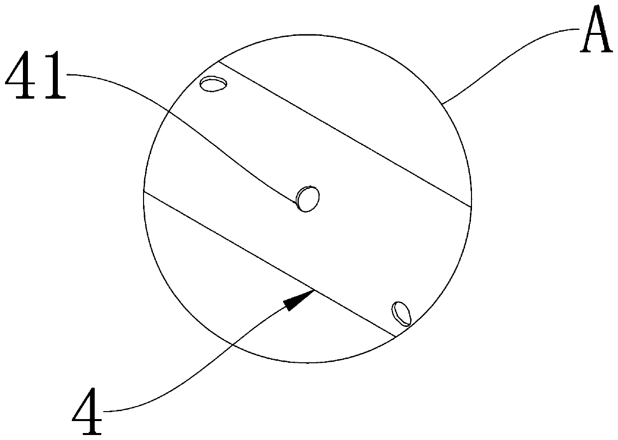
[0026] A multilumen central venous catheter, such as figure 1 and figure 2 As shown, a first branch conduit 1 is included, a second branch conduit 2 is provided on one side of the first branch conduit 1, a connector 3 is provided at one end of the first branch conduit 1 and the second branch conduit 2, and the first branch conduit 1 and one end of the second branch conduit 2 communicate with the inside of the connector 3, the two sides of the connector 3 are closely bonded with lugs 31, the lugs 31 are provided with a through hole 311, and the front side of the connector 3 is provided with There is a main conduit 4, and one end of the main conduit 4 communicates with the interior of the connector 3, and a plurality of side holes 41 are opened on the peripheral outer wall of the main conduit 4 near the front end.
[0027] Specifically, both the first branch catheter 1 and the second branch catheter 2 communicate with the main catheter 4, which is convenient for drainage and i...
Embodiment 2
[0030] As the second embodiment of the present invention, the difference from Embodiment 1 lies in that the radii of the plurality of side holes 41 are all different.
[0031] What needs to be added is that the multiple side holes 41 with different diameters are more conducive to infusion and drainage, and reduce the occurrence of pipeline blockage.
Embodiment 3
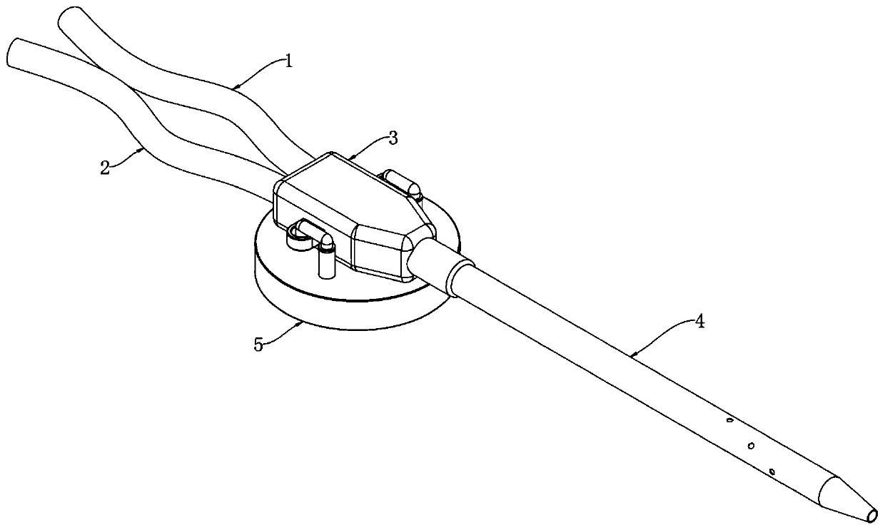
[0033] As a third embodiment of the present invention, in order to facilitate fixing the connector 3, the inventor has provided a fixer 5, such as Figure 3 to Figure 5 As shown, a fixer 5 is provided below the connector 3, and two symmetrical sleeves 51 are closely bonded to the top surface of the fixer 5. A sleeve rod 52 is arranged inside the sleeve sleeve 51, and the top surface of the sleeve rod 52 is Tightly bond the limit ring 54, the periphery of the sleeve rod 52 is provided with a spring 53, the bottom of the spring 53 is tightly bonded to the inner bottom surface of the sleeve 51, the top of the spring 53 is closely bonded to the bottom surface of the limit ring 54, and the limit The top surface of the ring 54 is tightly bonded with a pressure rod 55, one end of the pressure rod 55 is located in the through hole 311, the bottom surface of the holder 5 is provided with a groove 56, and the groove 56 is embedded with a sponge 57, and the bottom surface of the holder 5 ...
PUM
 Abstract
Description
Claims
Application Information
 - R&D Engineer
- R&D Manager
- IP Professional
- Industry Leading Data Capabilities
- Powerful AI technology
- Patent DNA Extraction
Browse by: Latest US Patents, China's latest patents, Technical Efficacy Thesaurus, Application Domain, Technology Topic.
© 2024 PatSnap. All rights reserved.Legal|Privacy policy|Modern Slavery Act Transparency Statement|Sitemap