Sludge chunk crusher

A pulverizer and sludge technology, applied in the direction of solid separation, filter screen, grid, etc., can solve the problems of reducing pulverization efficiency and inconvenient processing, and achieve the effect of improving pulverization efficiency.

Active Publication Date: 2019-05-31
湖州欧汇再生资源科技有限公司
View PDF10 Cites 8 Cited by
  • Summary
  • Abstract
  • Description
  • Claims
  • Application Information

AI Technical Summary

Problems solved by technology

[0003] In order to overcome the disadvantages that mechanical crushing of sludge can only be roughly crushed and broken up, it is difficult to complete the crushing of sludge lumps meticulously and fully, which w...

Method used


Image

  • Sludge chunk crusher
  • Sludge chunk crusher
  • Sludge chunk crusher

Examples


Embodiment 1

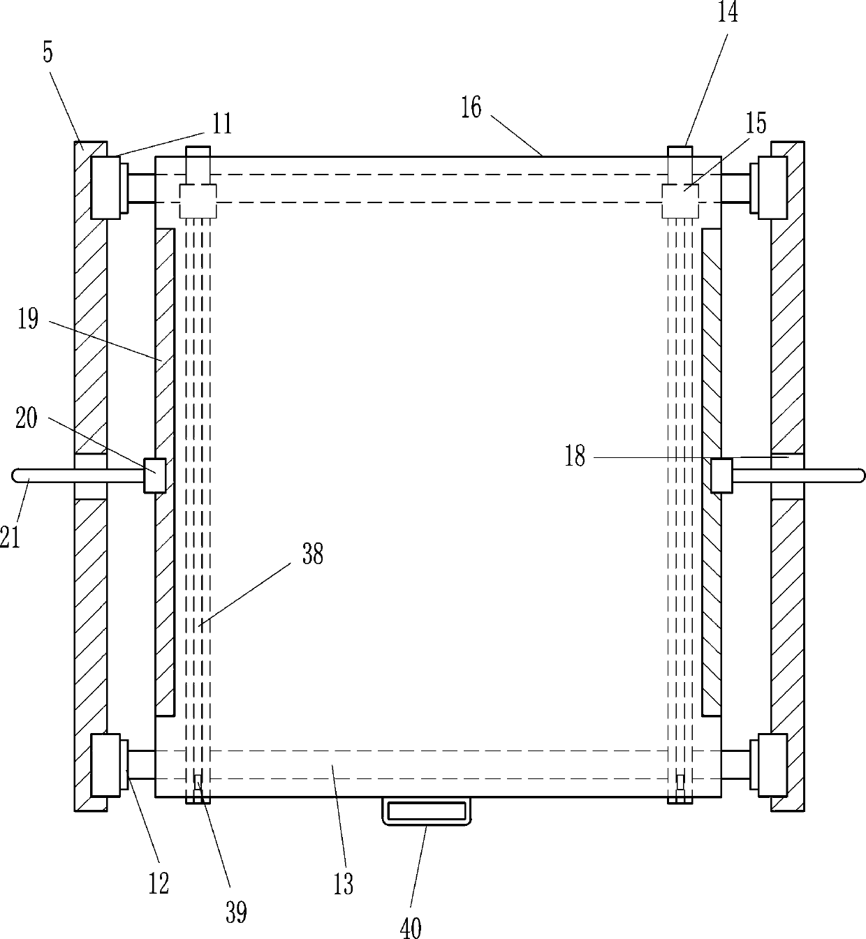
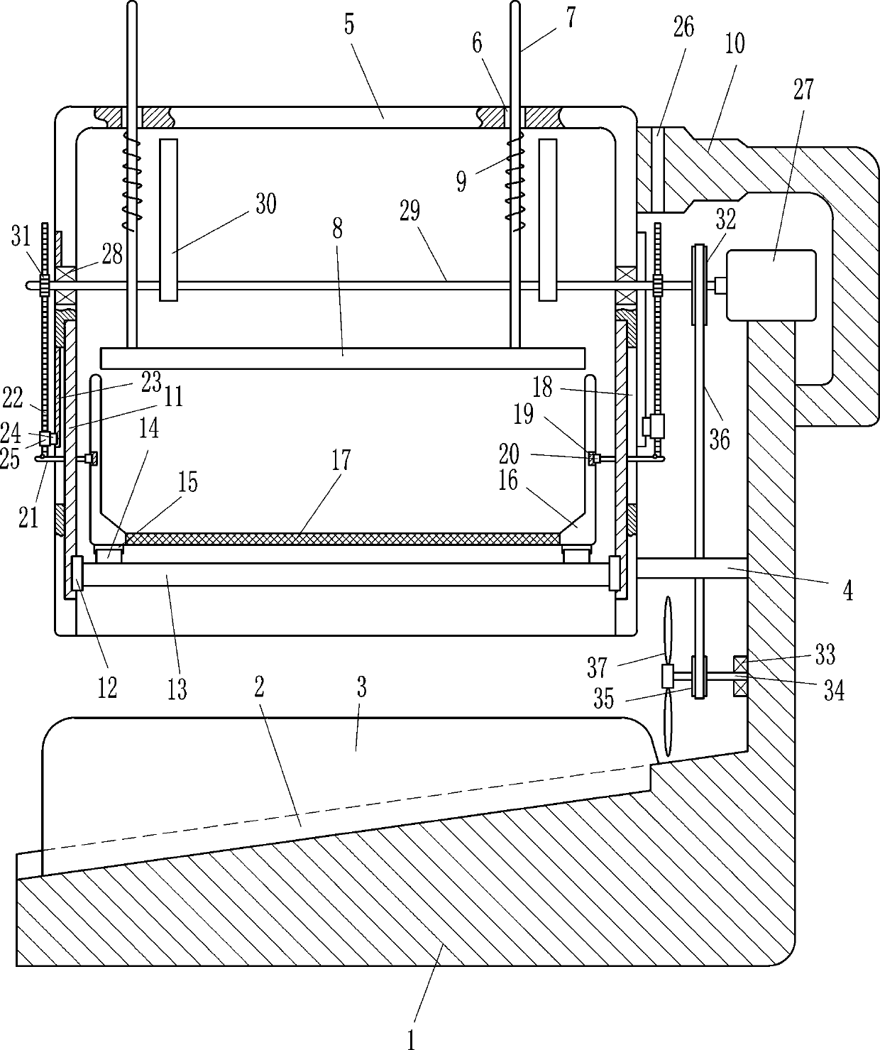
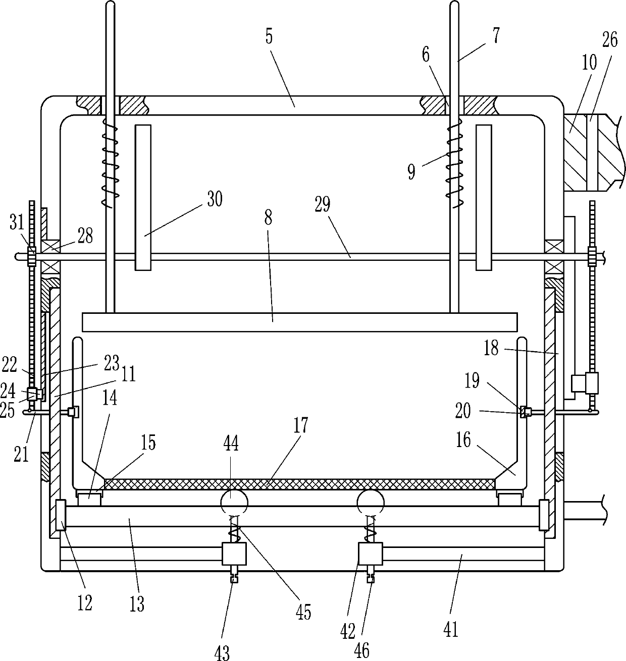
[0021] A sludge block crusher, such as Figure 1-3As shown, it includes a mounting frame 1, a baffle plate 3, a pole 4, a frame body 5, a guide rod 7, a pressure plate 8, a first spring 9, a concave frame 10, a first slide rail 11, a first slider 12, Connecting plate 13, second slide rail 14, second slide block 15, placement frame 16, screen plate 17, third slide rail 19, third slide block 20, first insertion rod 21, rack 22, fourth slide rail 23. The fourth slider 24, the ferrule 25, the motor 27, the first bearing seat 28, the first rotating shaft 29, the cam 30 and the gear 31. There is a chute 2 in the middle of the bottom of the installation frame 1 that can transport crushed sludge , the chute 2 is left low and the right is high, and the bottom, front and rear sides of the mounting frame 1 are equipped with baffles 3 that act as a barrier. The pole 4 is fixed on the lower right side of the mounting frame 1, and the frame body 5 Set on the left end of the pole 4, the lef...

Embodiment 2

[0023] A sludge block crusher, such as Figure 1-3 As shown, it includes a mounting frame 1, a baffle plate 3, a pole 4, a frame body 5, a guide rod 7, a pressure plate 8, a first spring 9, a concave frame 10, a first slide rail 11, a first slider 12, Connecting plate 13, second slide rail 14, second slide block 15, placement frame 16, screen plate 17, third slide rail 19, third slide block 20, first insertion rod 21, rack 22, fourth slide rail 23. The fourth slider 24, the ferrule 25, the motor 27, the first bearing seat 28, the first rotating shaft 29, the cam 30 and the gear 31. There is a chute 2 in the middle of the bottom of the installation frame 1 that can transport crushed sludge , the chute 2 is left low and the right is high, and the bottom, front and rear sides of the mounting frame 1 are equipped with baffles 3 that act as a barrier. The pole 4 is fixed on the lower right side of the mounting frame 1, and the frame body 5 Set on the left end of the pole 4, the le...

Embodiment 3

[0026] A sludge block crusher, such as Figure 1-3 As shown, it includes a mounting frame 1, a baffle plate 3, a pole 4, a frame body 5, a guide rod 7, a pressure plate 8, a first spring 9, a concave frame 10, a first slide rail 11, a first slider 12, Connecting plate 13, second slide rail 14, second slide block 15, placement frame 16, screen plate 17, third slide rail 19, third slide block 20, first insertion rod 21, rack 22, fourth slide rail 23. The fourth slider 24, the ferrule 25, the motor 27, the first bearing seat 28, the first rotating shaft 29, the cam 30 and the gear 31. There is a chute 2 in the middle of the bottom of the installation frame 1 that can transport crushed sludge , the chute 2 is left low and the right is high, and the bottom, front and rear sides of the mounting frame 1 are equipped with baffles 3 that act as a barrier. The pole 4 is fixed on the lower right side of the mounting frame 1, and the frame body 5 Set on the left end of the pole 4, the le...


PUM


Abstract

The invention relates to a crusher, in particular to a sludge chunk crusher. The sludge chunk crusher is used for achieving the technical purposes that crushing can be convenient to carry out, and thecrushing efficiency can be improved. According to the technical scheme, the sludge chunk crusher comprises a mounting rack, baffles, a supporting rod, a frame body, a guide rod, a pressing rod and the like. A sliding groove capable of being used for conveying crushed sludge is formed in the middle of the bottom of the interior of the mounting rack. The sliding groove is arranged with the left part low and the right part high. The baffles used for blocking are installed on the front side and the rear side of the bottom of the interior of the mounting rack. The supporting rod is fixed to the lower part of the right side face of the interior of the mounting rack. According to the sludge chunk crusher, because sludge chunks are crushed in the manner that the pressing plate moves downwards anda containing frame moves upwards, the sludge chunks can be conveniently crushed, crushed sludge can be screened through a mesh plate, and then the crushing efficiency of the sludge chunks can be improved; and because wind power generated by rotating blades can quicken leftward conveying of the crushed sludge, the phenomenon that crushing on the sludge chunks is hindered because the crushed sludgepiles up can be avoided.

Description

technical field [0001] The invention relates to a grinder, in particular to a sludge block grinder. Background technique [0002] With the continuous improvement of the level of urbanization, the construction of sewage treatment facilities has been developed at a high speed. At present, when sludge is treated, the sludge is usually dried, and then the sludge is crushed and broken up by machinery. Pulverization of sludge can only be roughly crushed and broken up, and it is difficult to complete the pulverization of sludge lumps carefully and fully, which will bring inconvenience to subsequent processing and reduce the crushing efficiency. In order to fully pulverize sludge lumps, For this reason, people will screen the pulverized sludge block by machinery, but it will increase people's workload. Contents of the invention [0003] In order to overcome the disadvantages that mechanical crushing of sludge can only be roughly crushed and scattered, it is difficult to complete ...

Claims


Application Information

Patent Timeline
IPC IPC(8): B02C1/14B02C23/16B02C23/20B07B1/54
Inventor 付三连
Owner 湖州欧汇再生资源科技有限公司
Why Eureka
Try Eureka