Oscillating arc tracking welding system based on dual gyroscopes
A welding system and double gyroscope technology, applied in the direction of arc welding equipment, welding equipment, welding rod characteristics, etc., can solve the problems of low welding precision and limited welding torch accessibility
- Summary
- Abstract
- Description
- Claims
- Application Information
AI Technical Summary
Problems solved by technology
Method used
Image

Examples
Embodiment Construction
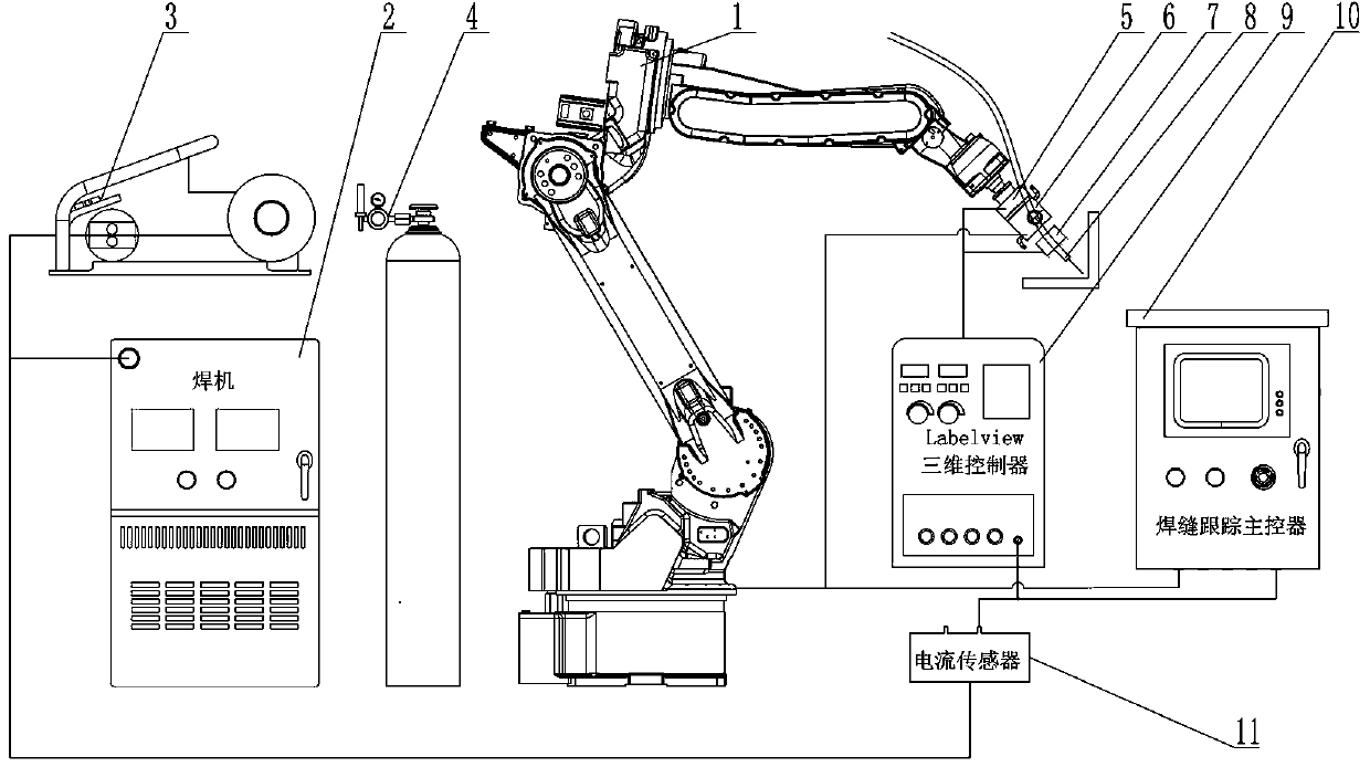
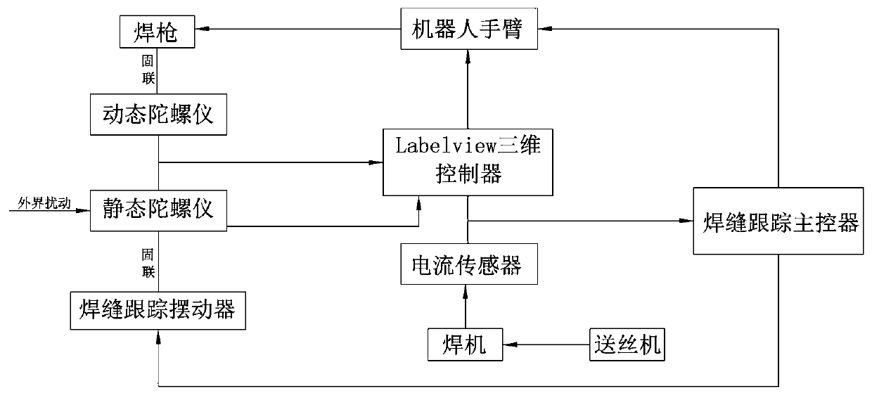
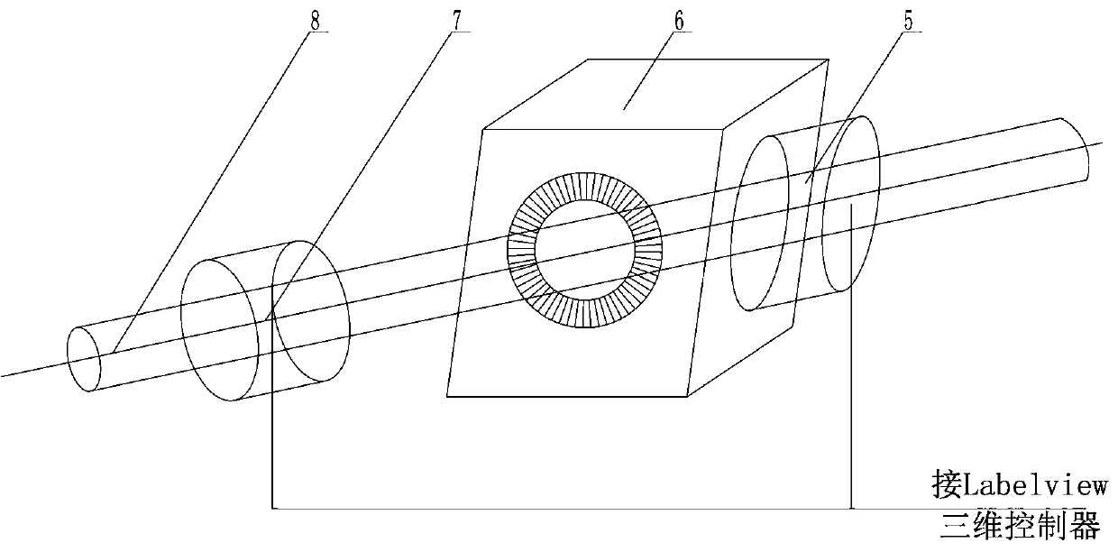
[0043] Such as Figure 1 ~ Figure 3 Among them, a swing arc tracking welding system based on double gyroscopes, which includes a welding machine 2 connected to the welding robot arm 1, a wire feeder 3 connected to the welding machine 2, and a gas cylinder 4 for supplying gas to the welding machine, The front end of the welding robot arm 1 is provided with a static gyroscope 5, a weld seam tracking oscillator 6, a dynamic gyroscope 7 and a welding torch 8 connected in sequence; the static gyroscope 5 and the dynamic gyroscope 7 are connected to a controller 9, and the weld seam The tracking oscillator 6 is connected with the seam tracking main controller 10, and the welding seam tracking main controller 10 is connected with the controller 9; Er current sensor 11. The structure is simple, by sequentially connecting the static gyroscope 5, the welding seam tracking oscillator 6, the dynamic gyroscope 7 and the welding torch 8 at the front end of the welding robot arm 1 of the os...
PUM
 Abstract
Description
Claims
Application Information