Method of calibrating six-dimensional force sensor at tail end of industrial robot

A six-dimensional force sensor and industrial robot technology, which is applied in the direction of manipulators, manufacturing tools, program control manipulators, etc., can solve the problems of inability to install the sensor, cannot guarantee the Z-axis installation angle of the sensor coordinate system, and calibration, so as to shorten the calibration time , improve precision, improve the effect of accuracy

Active Publication Date: 2019-05-31
HUAZHONG UNIV OF SCI & TECH
View PDF7 Cites 23 Cited by
  • Summary
  • Abstract
  • Description
  • Claims
  • Application Information

AI Technical Summary

Problems solved by technology

The data directly measured by the six-dimensional force sensor is based on its own coordinate system, and the industrial robot also has its own inherent coordinate system. There is a base coordinate system and an end flange coordinate system. Install the six-dimensional force sensor on the end flange of the robot. The Z axis of the sensor coordinate system and the Z axis of the end flange coordinate system can be guaranteed to be coaxial through the mechanical connector, but the installation angle of the Z axis between the sensor coordinate system and the end flange coordinate system cannot be guaranteed
And it is impossible to calibrate the sensor installation angle

Method used


Image

  • Method of calibrating six-dimensional force sensor at tail end of industrial robot
  • Method of calibrating six-dimensional force sensor at tail end of industrial robot
  • Method of calibrating six-dimensional force sensor at tail end of industrial robot

Examples


Embodiment Construction

[0033] In order to make the object, technical solution and advantages of the present invention clearer, the present invention will be further described in detail below in conjunction with the accompanying drawings and embodiments. It should be understood that the specific embodiments described here are only used to explain the present invention, not to limit the present invention. In addition, the technical features involved in the various embodiments of the present invention described below can be combined with each other as long as they do not constitute a conflict with each other.

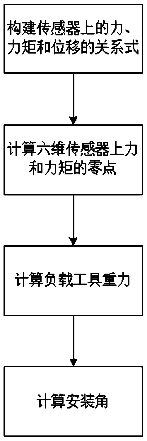
[0034] figure 1 It is a flow chart of the six-dimensional force sensor calibration method at the end of the robot constructed according to the preferred embodiment of the present invention. As shown in the figure, the following steps specifically illustrate the derivation process of the method of the present invention:

[0035] Step 1: Control the robot to change different postures, record the...


PUM


Abstract

The invention belongs to the field of industrial robot calibration and discloses a method of calibrating a six-dimensional force sensor at the tail end of an industrial robot. The method comprises thefollowing steps of (a) in the measurement process of the six-dimensional force sensor, constructing a relational expression of a force, a torque and displacement measured by the sensor and a relational expression of zero values of the force and the torque on the sensor and a mass center of a load tool; (b) acquiring data of the forces and the torques measured by the six-dimensional force sensor under multiple postures, and performing calculation with a least square method to obtain the zero values of the force and the torque of the six-dimensional sensor; (c) constructing a relational expression about the gravity of the load tool and performing calculation; and (d) constructing a relational expression about installation angles of a sensor coordinate system and a tail end flange coordinatesystem along a Z axis and performing calculation. By adopting the method, the calibration time is shortened, and the measurement precision is improved after a calibration result is compensated.

Description

technical field [0001] The invention belongs to the field of industrial robot calibration, and more specifically relates to a calibration method for a six-dimensional force sensor at the end of an industrial robot. Background technique [0002] Industrial robots are widely used in various fields of industrial production. In some tasks that require industrial robots to be in contact with the environment (such as grinding, polishing, assembly, etc.), simple position control cannot meet the needs of the task. For example, in grinding applications, high Rigid robots may cause damage to the ground workpiece when performing position control. Therefore, it is necessary for the robot to have the function of controlling the contact force with the environment. Existing implementations generally install a six-dimensional force sensor at the end of the robot to measure the force of the tool at the end of the robot during the working process to complete force control. [0003] The six-...

Claims


Application Information

Patent Timeline
Patent Type & Authority Applications(China)
IPC IPC(8): B25J9/16B25J13/08
Inventor 高培阳朱志红
Owner HUAZHONG UNIV OF SCI & TECH
Why Eureka
Try Eureka