
Quick dismounting machine for deep cavity and belt column plastic products from correcting assistive devices

A deep cavity, dismantling machine technology, applied in the coating and other directions, can solve the problems of easily damaged products, poor insertion, long time consumption, etc., to ensure the balance of force, prevent scratched products, and avoid the effect of tilting again.

Pending Publication Date: 2019-05-31
洛阳力诺模具有限公司
View PDF0 Cites 0 Cited by
  • Summary
  • Abstract
  • Description
  • Claims
  • Application Information

AI Technical Summary

Problems solved by technology

For products with deep cavities and columns, when the accessories and the product are assembled together, heated and then cooled, the product will be tightly wrapped on the accessories due to the generation of wrapping force, and it is difficult to remove it by hand. It is removed by knocking, and the product is easy to be damaged. The whole process is time-consuming, laborious and inefficient.
E.g image 3 The socket insulator part in the aerospace electrical connector shown has multiple tall single columns inside, and the inner cavity is deep. Because of the strict assembly requirements for the center distance of the column holes, and the product is inclined after molding , it is easy to cause bad mating
In order to correct the inclination of the above-mentioned columns, technicians will make corresponding correction aids according to the deformation size of the above-mentioned socket insulator parts. Although the correction with aids can achieve excellent results, it takes a lot of effort to move the product from When the accessories are separated, workers often use improper tools to insert the product to knock out the accessories, which takes a long time and has a high damage rate

Method used


Image

  • Quick dismounting machine for deep cavity and belt column plastic products from correcting assistive devices
  • Quick dismounting machine for deep cavity and belt column plastic products from correcting assistive devices
  • Quick dismounting machine for deep cavity and belt column plastic products from correcting assistive devices

Examples


Embodiment Construction

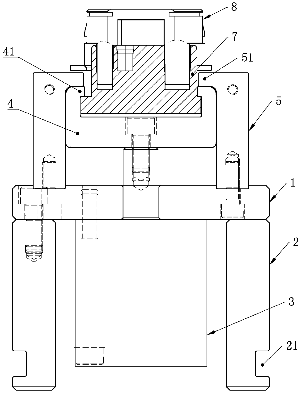
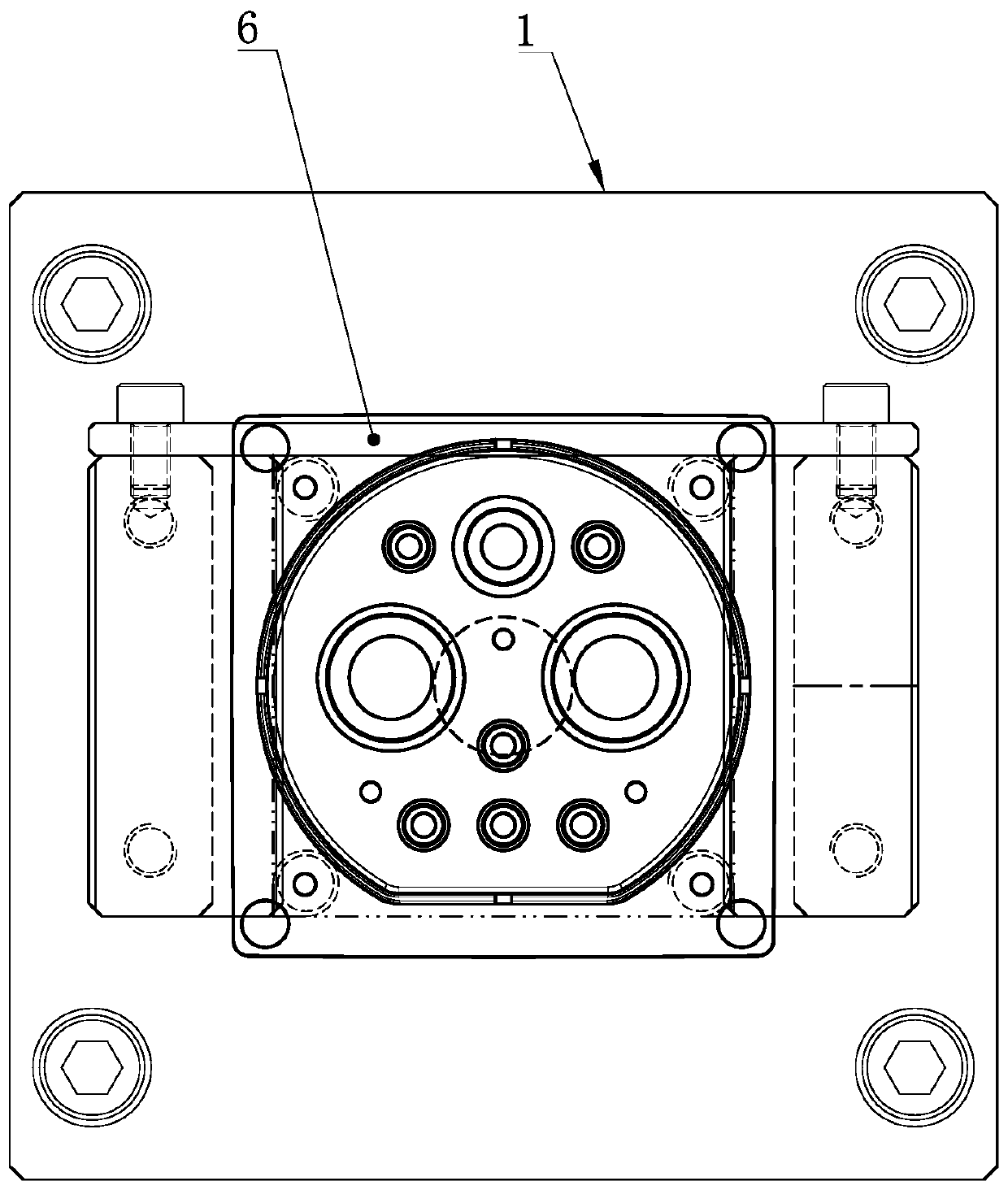
[0020] In order to further explain the technical means and effects of the present invention to achieve the intended purpose of the invention, the following will be combined with the accompanying drawings and preferred embodiments to describe a kind of deep cavity and post-type plastic product correction aids proposed according to the present invention. Its specific embodiment, structure, feature and effect thereof of quick disassembly machine are as follows in detail.

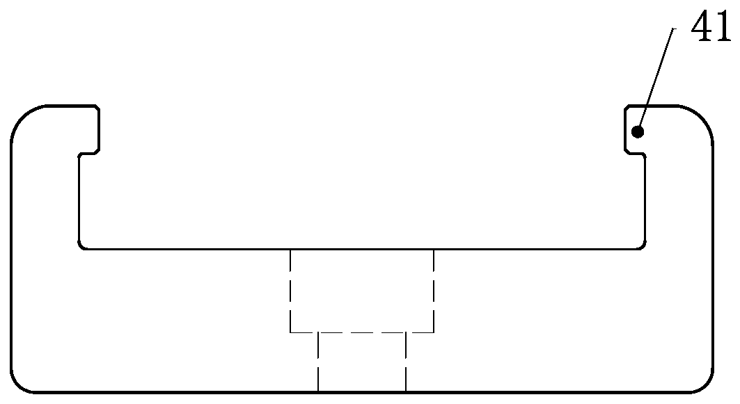
[0021] see Figure 1 to Figure 2 , a quick dismantling machine for correcting aids for deep cavity and plastic products with columns according to the present invention, which is used to quickly and non-injuryly separate orthodontic aids from deep cavity and plastic products with columns, which includes a bottom plate 1, the Both sides of the bottom of the bottom plate 1 are symmetrically installed with two brackets 2 through bolts, and the outer side of the bracket is provided with a fixing groove 21 along the ...


PUM


Abstract

The invention discloses a quick dismounting machine for a deep cavity and belt column plastic products from correcting assistive devices. The quick dismounting machine comprises a bottom plate (1), wherein the two sides of the bottom of the bottom plate (1) are symmetrically equipped with brackets (2); fixed slots (21) are formed in a length direction in the outer sides of the brackets (2); a gascylinder (3) positioned between the brackets (2) is mounted on the bottom plate (1); a piston rod of the gas cylinder (3) passes through the bottom plate (1) and then is fixedly connected with a movable block (4); a pair of limiting frames (5) is symmetrically arranged on the bottom plate (1); the tops of the limiting frames (5) are bent inwards to form supporting limiting arms (51); the two sidesof the movable block (4) extend upwards, and are bent inwards to form assistive device positioning clamping arms (41); and the movable block (4) is positioned between the two limiting frames (5) andis in sliding fit to the limiting frames (5). According to the technical scheme adopted by the invention, the invention discloses the quick dismounting machine for conveniently separating the deep cavity and the belt column plastic products from the matched correcting assistive devices.

Description

technical field [0001] The invention belongs to the field of dismantling equipment for correction aids, in particular to a quick disassembly machine for correction aids for plastic products with deep cavities and columns. Background technique [0002] Plastic products are used in a wide range of applications. During the production process, products often experience unavoidable warping and deformation due to structural problems, which seriously affects installation and use. For this type of product, the most common solution is to make auxiliary equipment to correct the product. Through random production or post-heating of the product in the oven, the deformed product is loaded into the calibration auxiliary equipment so as to reach the qualified or acceptable use range. For products with deep cavities and columns, when the accessories and the product are assembled together, heated and then cooled, the product will be tightly wrapped on the accessories due to the generation of...

Claims


Application Information

Patent Timeline
Patent Type & Authority Applications(China)
IPC IPC(8): B29C37/00
Inventor 张东伟张翠华
Owner 洛阳力诺模具有限公司
Learn More