Swirl blade, swirl fan, swirl pipeline and preparing method of swirl pipeline

A technology of swirling blades and fans, which is applied in heat exchange equipment, lighting and heating equipment, heat transfer modification, etc., and can solve the problems that the effect of tube heat exchange needs to be further improved

Pending Publication Date: 2019-05-31
GUANGDONG SUOTE ENERGY TECH CO LTD +1
View PDF9 Cites 1 Cited by
  • Summary
  • Abstract
  • Description
  • Claims
  • Application Information

AI Technical Summary

Problems solved by technology

However, the existing designs of various inserts are still insufficient in making the fluid rotate and advance, and the effect of tubular heat exchange still needs to be further improved.

Method used


Image

  • Swirl blade, swirl fan, swirl pipeline and preparing method of swirl pipeline
  • Swirl blade, swirl fan, swirl pipeline and preparing method of swirl pipeline
  • Swirl blade, swirl fan, swirl pipeline and preparing method of swirl pipeline

Examples


Embodiment 1

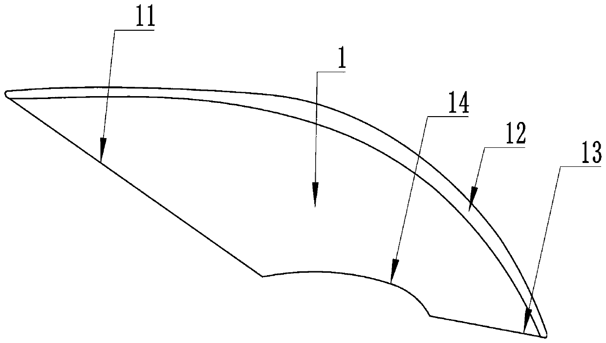
[0040] The first embodiment provides a swirl blade 1, please refer to figure 1 , the swirl blade 1 includes a leading edge 11 , a back arc 12 , a trailing edge 13 and an inner arc 14 which are connected end to end in sequence. The leading edge 11 faces the air intake direction of the swirl fan, and the trailing edge 13 faces the air outlet direction of the swirl fan.

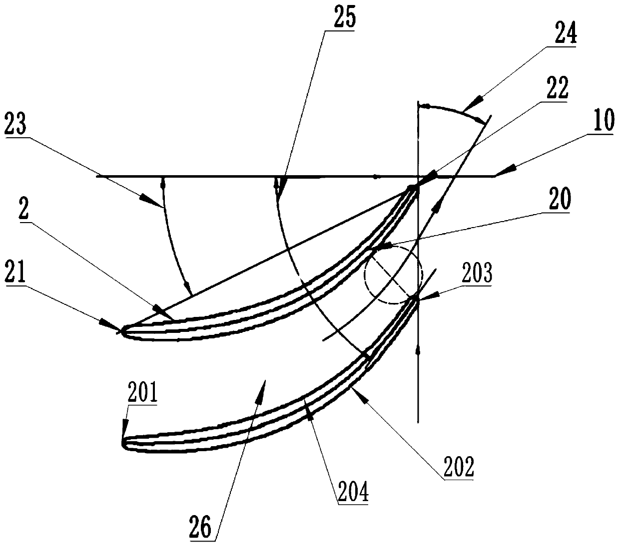
[0041] Please refer to figure 2 , the swirl vane 1 rotates around the rotation axis 10 . The projection of the swirl blade 1 on the cylindrical surface coaxial with the rotation axis 10 forms the blade profile line 2, and the blade profile line 2 is a closed curve, including a leading edge line 201, a back arc line 202, and a trailing edge line that are connected end to end in sequence 203 and inner arc 204. The intersection of the mid-arc line of the blade profile 2 and the leading edge line 201 is the leading edge point 21 , and the intersection of the mid-arc line of the blade profile 2 and the trailing e...

Embodiment 2

[0046] This embodiment provides a swirl fan, including a plurality of swirl blades 1 in the first embodiment.

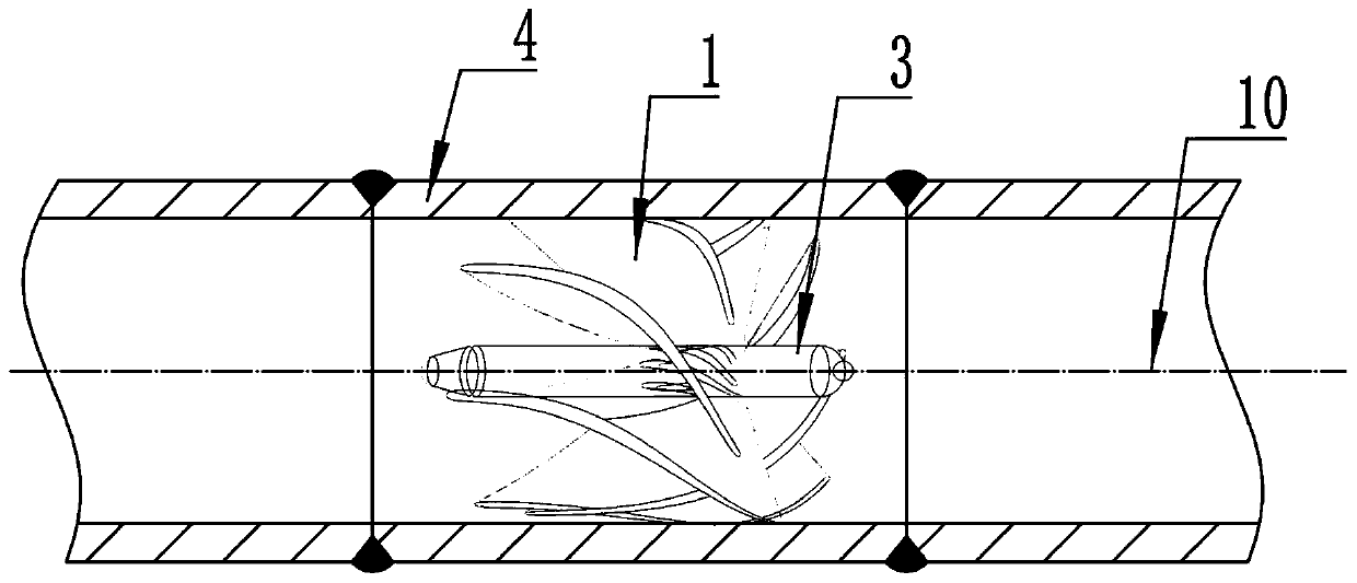
[0047] Please refer to image 3 , the swirl fan also includes a hub 3 . The plurality of swirl blades 1 are mounted on the hub 3 and are evenly distributed around the axis of the hub 3 . The axis of the hub 3 is the rotation axis 10 , and the inner arc 14 of the swirl blade 1 is fixedly connected to the hub 3 . Specifically, the hub 3 initially has an inner arc 14-shaped hole matching the shape of the inner arc 14 , and the inner arc 14 is inserted into the inner arc 14-shaped hole and fixedly connected to the hub 3 .

[0048] Please refer to figure 2 , the two adjacent swirl vanes 1 are the first swirl vane and the second swirl vane respectively, and the projections of the first swirl vane and the second swirl vane on the same cylindrical surface are respectively the first swirl vane type Wire( figure 2 The swirl vane profile above the swirl vane) and the sec...

Embodiment 3

[0056] This embodiment provides a swirl pipeline 4 and a preparation method thereof. The swirl fan provided in the second embodiment is installed in the swirl duct 4 .

[0057] Please refer to image 3 , a plurality of back arc 12-shaped line holes matching the shape of the back arc 12 of the swirl vane 1 are opened on the pipe wall of the swirl duct 4, and the back arc 12 of each swirl vane 1 is inserted into a corresponding back arc. 12-type wire hole, fixedly connected to the swirl pipe 4.

[0058] The preparation method of the swirl pipe 4 comprises the following steps:

[0059] prepare a plurality of swirl blades 1;

[0060] The swirl pipe 4 is divided into two parts along the axis;

[0061] A plurality of inner arc 14-shaped line holes are set on the hub 3, the inner arc 14 of each swirl blade 1 is inserted into the corresponding inner arc 14-shaped line hole, and the swirl blade 1 and the hub 3 are welded;

[0062] A plurality of back-arc 12-shaped line holes are o...


PUM


Abstract

The invention discloses a swirl blade. The swirl blade comprises a front edge, a back arc, a tail edge and an inner arc which are connected end to end in sequence, the swirl blade rotates around the rotating axis, the projection of the swirl blade on the cylinder face coaxial with the rotating axis forms a blade molded line, the blade molded line is a closed curve line, the crossed point of the middle arc line of the blade molded line and the front edge line is the front edge point, the crossed point of the middle arc line of the blade molded line and the tail edge line is the tail edge point,the included angle between the connection line of the front edge point and the tail edge point and the rotating axis is the blade mounting angle, when the radius of the cylinder face is gradually increased, the blade mounting angle is gradually increased, and meanwhile, the outlet airflow angle is gradually reduced; according to the swirl blade, in the radial direction, the blade mounting angle is gradually increased, the outlet airflow angle is gradually reduced, it can be ensured that after fluid flows through the swirl blade, the fluid carries out spiral motion in the circumferential direction at the higher speed, and pressure energy is converted into tangent and axial kinetic energy of fluid to the maximum degree.

Description

technical field [0001] The invention relates to the field of heat exchange, in particular to a swirling blade, a swirling fan, a swirling duct and a preparation method thereof. Background technique [0002] With the rapid development of modern industry, energy and environmental problems have become increasingly prominent. While developing clean energy and new-generation energy utilization technologies, countries around the world also pay more attention to opening up new ways to save energy. The application of enhanced heat transfer technology can not only save energy and protect the environment, but also greatly save investment costs. In the first version of energy transfer equipment, heat exchangers have been widely used in chemical, petroleum, power and atomic energy and other industrial sectors. Strengthening the heat transfer capacity of heat exchangers has always been valued by researchers, and corresponding enhanced heat exchangers have been derived. Thermal technolo...

Claims


Application Information

Patent Timeline
Patent Type & Authority Applications(China)
IPC IPC(8): F28F13/06F28F13/12
Inventor 康磊李海宾宋文婉周辉梁奇源韩敏芳夏云峰
Owner GUANGDONG SUOTE ENERGY TECH CO LTD
Why Eureka
Try Eureka