Supercharge Your Innovation With Domain-Expert AI Agents!

Method and system for controlling rotor speed of motor

A technology of motor rotor and control method, applied in electrical components, emergency protection circuit devices, etc., can solve the problems of motor power cut off, impeller speed drop, trouble, etc., and achieve the effect of preventing false braking

Inactive Publication Date: 2019-05-31
江苏施依洛通风设备有限公司
View PDF3 Cites 0 Cited by
  • Summary
  • Abstract
  • Description
  • Claims
  • Application Information

AI Technical Summary

Problems solved by technology

[0004] However, in the actual application process of the above-mentioned method of cutting off the power supply, since the actual chimney is exhausting smoke, there are easily large obstacles in the chimney. When the obstacle is discharged from the chimney, it touches the impeller and will Causes the speed of the impeller to drop to a certain speed instantly, and then when the obstacle is discharged from the chimney, the speed of the impeller returns to the original speed
When the above-mentioned speed sensor system is installed, the speed sensor senses the instantaneous speed drop when the obstacle is discharged from the chimney, which will also cause the power supply of the motor to be cut off, which requires people to turn on the motor again, which is troublesome

Method used


Image

  • Method and system for controlling rotor speed of motor
  • Method and system for controlling rotor speed of motor
  • Method and system for controlling rotor speed of motor

Examples


Embodiment 1

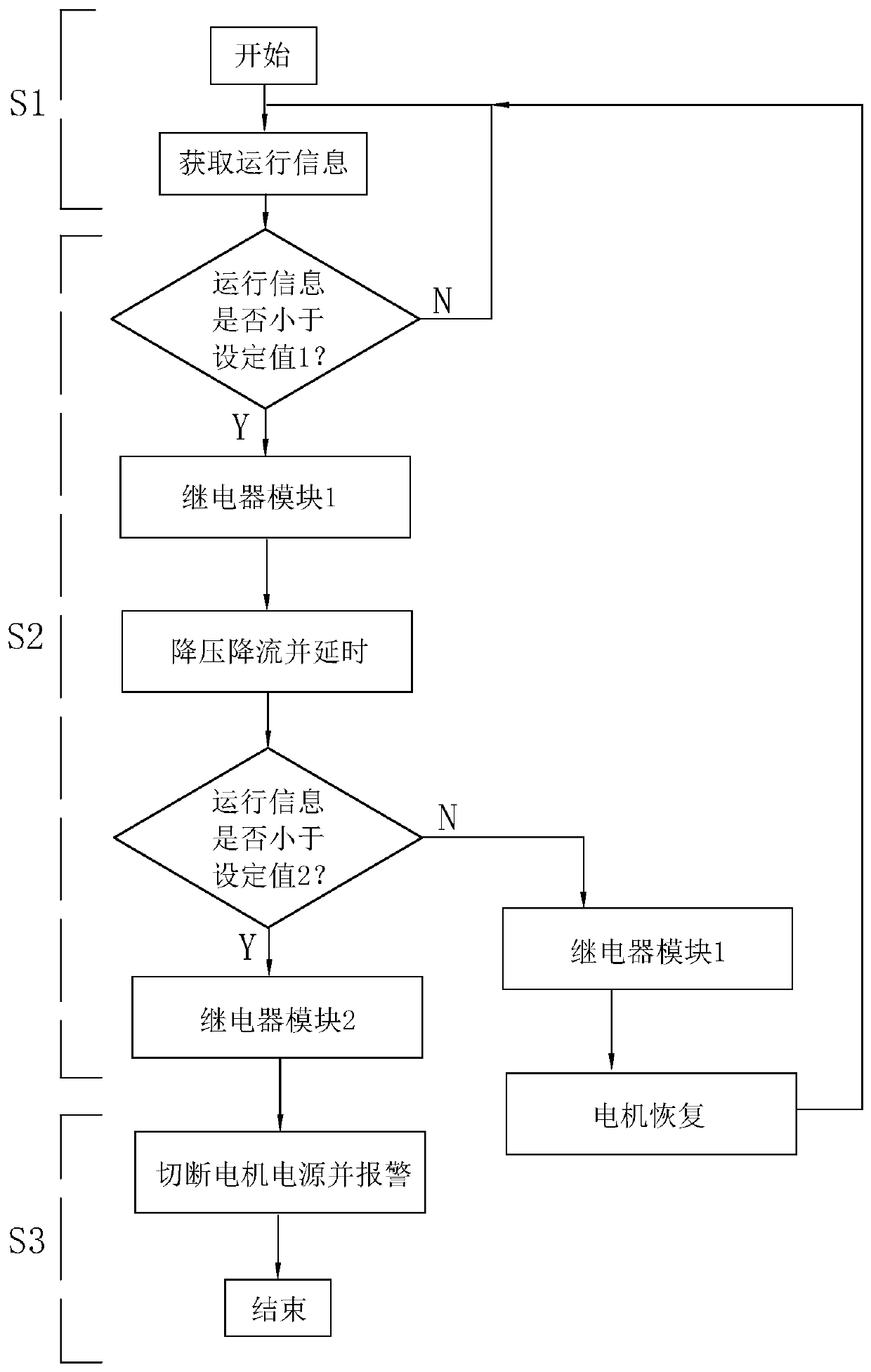
[0066] A method for controlling the rotor speed of a motor, mainly referring to a control method for controlling a DC motor that drives an impeller to rotate, such as a DC motor in a ceiling fan, such as a DC motor that drives an impeller in a chimney, combined with figure 1 and Figure 4 It can be seen that it mainly includes the following steps:

[0067] The first step S1: obtaining the operation information of the motor rotor in real time, the operation information in this embodiment refers to the real-time rotation speed information of the impeller.

[0068] Second step S2: According to the acquired real-time rotation speed information of the impeller, determine whether to cut off the power supply of the motor. Specifically, the analysis method is to compare the obtained rotational speed value with the set value 1, which refers to the normal rated rotational speed value of the motor under the rated voltage / rated current of the motor. When the obtained speed value is equa...

Embodiment 2

[0085] The difference between this embodiment and Embodiment 1 is that the operation information of the motor rotor acquired in S1 is the corresponding current value when the impeller rotates in real time.

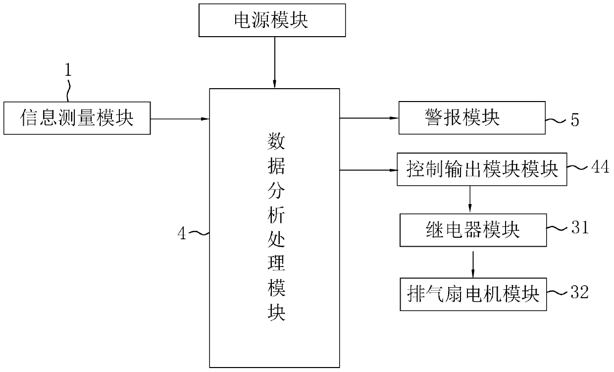
[0086] The setting value 1 in S2 refers to the rated current value of the motor, and the setting value 2 in S2 refers to the normal current value of the motor after voltage reduction. By configuring the information detection module 1 as a current value measurement module, the purpose of preventing false braking of the motor is achieved by analyzing the magnitude of the current when the motor is rotating.


PUM


Abstract

The invention relates to the technical field of motor control and discloses a method and system for controlling the rotor speed of a motor. The method comprises the following steps of S1, acquiring the operation information of the rotor of a motor in real time; S2, determining whether it is necessary to cut off the power supply of the motor according to the acquired operation information; when theobtained speed value is less than a set value 1, firstly reducing the power supply voltage and current of the motor and performing a time delay; when the time of reducing the supply voltage and current is greater than the predetermined time, comparing the obtained speed value with a set value 2; when the obtained speed value is equal to the set value 2, performing initialization to restore the normal power supply of the motor; and when the obtained speed value is less than the set value 2, cutting off the power supply of the motor. According to the above technical solution, when an impeller is actually used, an obstacle instantaneously blocks the impeller to lower the impeller speed is lowered such that the motor cannot be braked by mistake; the motor is braked and prevented from being burnt out only when the impeller is stuck and the speed continuously decreases.

Description

technical field [0001] The invention relates to the technical field of motor control, more specifically, it relates to a method and system for controlling the rotational speed of a motor rotor. Background technique [0002] A motor is an electromagnetic device that converts or transmits electrical energy according to the law of electromagnetic induction. The motor is represented by the letter M in the circuit. Its main function is to generate driving torque. As a power source for various machines, its main function is to convert electrical energy into mechanical energy. [0003] When the current motor is applied to the chimney to drive the impeller to rotate, the motor may be burned because the impeller may block obstacles during work. Therefore, the solution to this problem in the prior art is mainly by installing a rotational speed sensor to detect the rotational speed of the impeller, and when the rotational speed sensor senses that the rotational speed of the impeller d...

Claims


Application Information

Patent Timeline
Patent Type & Authority Applications(China)
IPC IPC(8): H02H7/08H02H7/093
Inventor 吕俊达董颂均庄擎
Owner 江苏施依洛通风设备有限公司
Features
  • R&D
  • Intellectual Property
  • Life Sciences
  • Materials
  • Tech Scout
  • Unparalleled Data Quality
  • Higher Quality Content
  • 60% Fewer Hallucinations
Learn More