A clock synchronization method, system and device for an Ethernet electrical port
A clock synchronization, Ethernet technology, applied in the field of network communication, can solve the problem that the electrical port module cannot recover the clock signal, etc.
- Summary
- Abstract
- Description
- Claims
- Application Information
AI Technical Summary
Problems solved by technology
Method used
Image
Examples
Embodiment 1
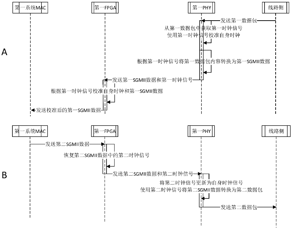
[0029] In network data transmission, the existing pluggable electrical port module has a built-in crystal oscillator, so the signal transmitted to the line side does not carry the clock signal of the system side, but the clock signal generated by the built-in crystal oscillator of the electrical port module. The signal is not necessarily completely synchronized with the system-side clock signal. Even if the electrical interface module includes a PHY capable of recovering the clock on the line side, since the SFP gold finger of the electrical interface module does not define clock input pins and clock output pins, it does not have the function of recovering clock signals from the system side. This embodiment provides a way to restore the clock signal of the Ethernet electrical port from the system side and the line side, which ensures the synchronization of the clock signals on the system side and the line side connected to the electrical port module, and ensures that clock synchr...
Embodiment 2
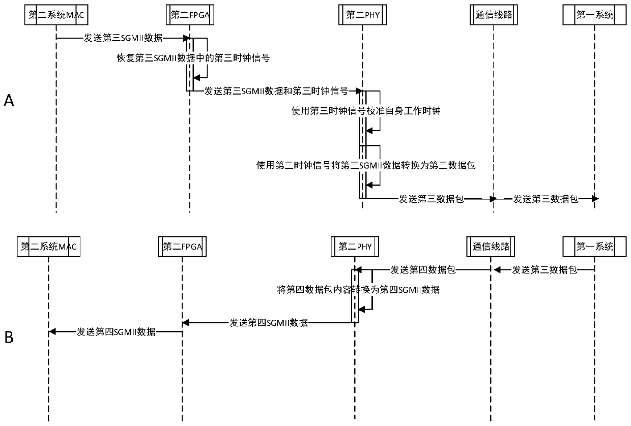
[0047] In network data transmission, in some cases, the data sending end and receiving end on both sides of the electrical port need to work in Master-Slave mode to achieve communication function requirements such as command distribution, parallel control, and error monitoring.
[0048] In an Ethernet data communication system, in order to facilitate multi-device communication or management, generally there is only one Master terminal, and there may be multiple Slave terminals. Therefore, when synchronizing Ethernet clocks, the clock at the Master end is generally used as the system operating clock, and the operating clocks at the Slave end and other devices in the system are calibrated.
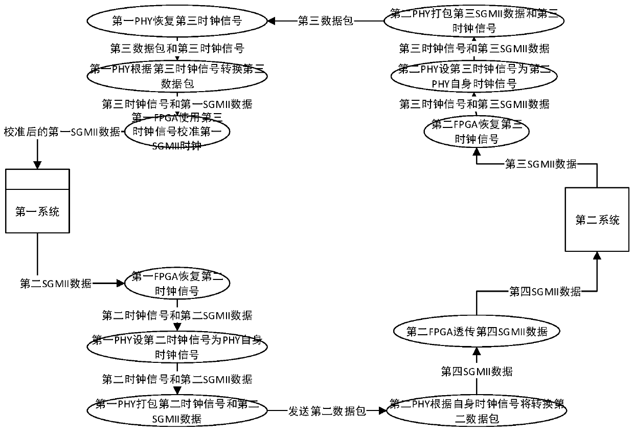
[0049] In some application scenarios of this embodiment, two systems exist simultaneously in the network: the first system and the second system.
[0050] The first system and the second system are respectively in one of the Master and Slave modes in the Master-Slave mode, and the two system...
Embodiment 3
[0074] In network data transmission, in some cases, when the systems on both sides of the communication work in Master-Slave mode, the related interface devices such as PHY also need to set the working mode to be consistent with the working mode of the local system. Realize synchronous communication.
[0075] In some actual usage scenarios of this embodiment, the first system works in the Master mode, and both the first FPGA and the first PHY also work in the Master mode. At this time, the first FPGA and the first PHY can directly obtain the system clock of the first system to calibrate their own working clock, and pack the clock signal into the communication data packet, and transmit it to the slave end, so that the slave end device can Perform clock synchronization calibration.
[0076] In some actual usage scenarios of this embodiment, the first system works in the Slave mode, and both the first FPGA and the first PHY also work in the Slave mode. When communicating with t...
PUM
 Abstract
Description
Claims
Application Information
 - R&D
- Intellectual Property
- Life Sciences
- Materials
- Tech Scout
- Unparalleled Data Quality
- Higher Quality Content
- 60% Fewer Hallucinations
Browse by: Latest US Patents, China's latest patents, Technical Efficacy Thesaurus, Application Domain, Technology Topic, Popular Technical Reports.
© 2025 PatSnap. All rights reserved.Legal|Privacy policy|Modern Slavery Act Transparency Statement|Sitemap|About US| Contact US: help@patsnap.com


