
3D printing mechanism

A 3D printing, stage technology, applied in 3D object support structure, additive manufacturing, manufacturing tools, etc., can solve the problems of immature and feasible technology, double the cost, increase the number of motors, etc., to meet the needs of large-scale high-precision Printing requirements, without sacrificing printing accuracy, the effect of increasing the printing area

Pending Publication Date: 2019-06-04
SOUTH CHINA UNIV OF TECH +1
View PDF0 Cites 3 Cited by
  • Summary
  • Abstract
  • Description
  • Claims
  • Application Information

AI Technical Summary

Problems solved by technology

However, if you want to increase the effective area of ​​printing, if you use the method of enlarging the projection surface, the dpi of the projection surface will be reduced and the printing accuracy will be greatly sacrificed. If you use multiple projectors to splice a large projection surface, the cost will double. Using mobile projection The method of instrument or optical path will increase the number of motors, destroying its simple structure, and the introduction of motors will increase the error. Obviously, they are not mature and feasible technologies, and cannot meet the needs of the general market.

Method used


Image

  • 3D printing mechanism
  • 3D printing mechanism
  • 3D printing mechanism

Examples


Embodiment 1

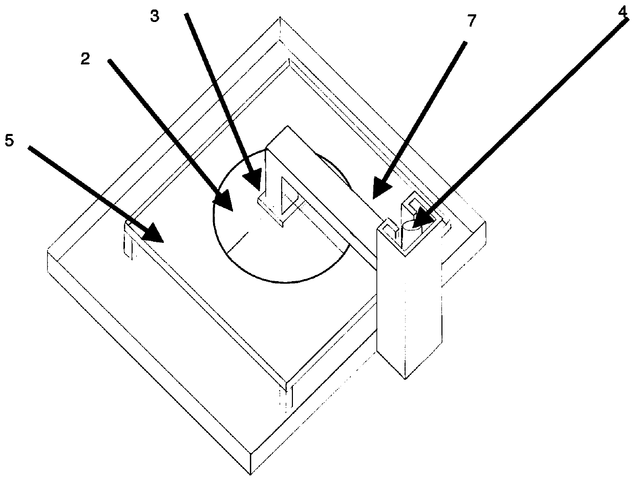
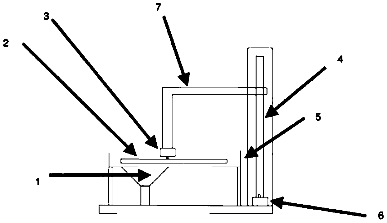
[0025] Such as Figure 1-2 As shown, a 3D printing mechanism includes a printing part and a lifting part;

[0026] The printing part includes a circular stage 2, a first motor 3, a digital light processing projector 1, and a resin tank 5;

[0027] The stage is connected to the motor of the stage, and the motor of the stage drives the stage to rotate when it works;

[0028] A projection plane projected by the digital light processing projector passes through the resin tank and is printed on at least part of the stage;

[0029] The lifting part includes a second motor, a load-bearing shaft of the object stage, a screw rod 4 threadedly connected with the load-bearing shaft, and a limit plate. The second motor drives the screw rod to rotate, and then drives the load-bearing shaft of the object stage to move along the length direction of the screw rod , so that the stage moves along the length of the screw rod.

[0030] The working process of the present invention: the projectio...

Embodiment 2

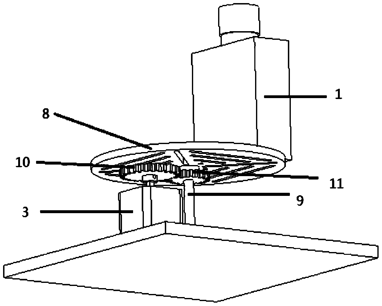
[0032] Such as Figure 3-4 As shown, the first motor can be changed to drive the rotation of the projector, thereby increasing the printing area, specifically: a 3D printing mechanism, including a printing part and a lifting part; the printing part includes a fixed plate 8, a support rod 9. The fixed plate is installed on the support rod and can rotate relative to the support rod; the projector is installed on the fixed plate; the output shaft of the first motor is installed with the first gear 10, and the connection between the fixed plate and the support rod is installed with the first The second gear 11, the second gear is relatively fixed to the fixed plate, the first gear meshes with the second gear; the first motor drives the fixed plate to rotate and further drives the projector to rotate. The fixed plate is provided with several hollow structures to facilitate the fixing of the projector.

[0033] Other structural components and connections of this embodiment are the ...


PUM


Abstract

The invention discloses a 3D printing mechanism. The 3D printing mechanism comprises a printing part and a lifting part; the printing part comprises a carrying table, a first motor, a digital opticalprocessing projector and a resin tank; the carrying table and a carrying table motor are connected, and when the carrying table motor is in operation, the carrying table is driven to rotate; a projection plane projected by the digital optical processing projector penetrates through the resin groove and is printed on at least part of the carrying table; and the lifting part is partly connected to the carrying table of the printing part. The 3D printing mechanism expands the effective area of printing to several times of the original effective areas of printing on the basis of maintaining the resolution ratio, and realizes microlithographic 3D printing with a larger size.

Description

technical field [0001] The invention belongs to the technical field of microlithography 3D printing, and in particular relates to a 3D printing mechanism. Background technique [0002] Digital Light Processing (DLP) is a 3D printing technology that has emerged in recent years. When processing products, digital micromirror elements are used to project cross-sectional graphics of products onto the surface of liquid bright resin, so that the irradiated resin is cured layer by layer. Digital light processing projectors use digital micromirror device DMD chips as imaging devices. An instrument that realizes reflective projection by adjusting the angle of the micromirror. The 3D printers of miniature digital light processing projection devices currently on the market use a single-sided superimposed structure. The graphics of each layer of the printed model are only formed by projection and solidification of a cut surface. The printing surface and the projection surface overlap. T...

Claims


Application Information

Patent Timeline
Patent Type & Authority Applications(China)
IPC IPC(8): B29C64/20B29C64/124B33Y30/00
Inventor 赵明廖邵伟周绍林苏启聪李富华
Owner SOUTH CHINA UNIV OF TECH
Learn More