
Cylinder head stamping mark pressing tool and method

A cylinder head and steel stamping technology, applied in stamping, printing, etc., can solve problems such as poor knocking quality, uneven depth of steel stamp marks, skewed fonts, etc., to achieve the effect of improving efficiency and quality, improving appearance quality, and meeting forming requirements

Active Publication Date: 2020-12-29
CSSC MARINE POWER
View PDF4 Cites 0 Cited by
  • Summary
  • Abstract
  • Description
  • Claims
  • Application Information

AI Technical Summary

Problems solved by technology

[0004] 1. The efficiency is low. The operator needs to select a suitable stencil from dozens of stencils, and hit them one by one with a hammer at a suitable position in the cylinder head marking area. It takes at least 30 seconds from taking out a stencil to completing the stencil knocking, which is time-consuming strenuous
[0005] 2. The quality of knocking is poor. Because the force of the artificial hammer hitting the stamped font cannot be kept consistent, the stamped logo on the cylinder head has quality problems such as uneven depth and skewed fonts; at the same time, manual operation cannot guarantee the quality of each adjacent stamped stamp. The spacing between the marks is equal, and the line spacing of each line of stamped marks is equal, which cannot achieve the uniform effect of stamped marks, and even the knocked stamped marks cannot be recognized
Poor steel stamp marks on the cylinder head seriously affect the appearance quality of the diesel engine

Method used


Image

  • Cylinder head stamping mark pressing tool and method
  • Cylinder head stamping mark pressing tool and method
  • Cylinder head stamping mark pressing tool and method

Examples


Embodiment Construction

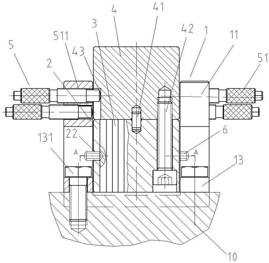
[0034] The present invention will be further described below in conjunction with the accompanying drawings and the embossed embodiment of stamping on the L23 type marine diesel engine cylinder head.

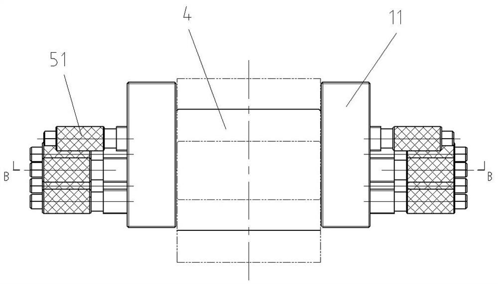
[0035] Such as Figure 2 ~ Figure 6 As shown, this embodiment includes a positioning bracket 1, a stamped font support block 2, a plurality of stamped fonts 3, a pressing block 4 and a stamped font line spacing adjustment mechanism 5, and the positioning bracket 1 is in the shape of a groove with an opening facing the front side, including two sides. Vertical side panels 11 and bottom horizontal panels 12, such as Figure 4 As shown, there is a gap at the bottom of the vertical side plate 11, and the bottom side of the gap is a connecting plate 13, and the connecting plates 13 on both sides of the bottom of the positioning bracket 1 are respectively fixed on both sides of the steel stamp mark of the cylinder head 10 by screws 131.

[0036] Such as Figure 5As shown, the longitu...


PUM


Abstract

The invention discloses a cylinder cover steel seal mark pressing tool. The cylinder cover steel seal mark pressing tool comprises a positioning support, a steel seal matrix supporting block, a plurality of steel seal matrixes, a pressing block and a steel seal matrix line spacing adjusting mechanism, wherein the bottom of the positioning support is fixed on the two sides of a steel seal mark partof a cylinder cover, the plurality of transversely-adjacent steel seal matrixes are fixed in the steel seal matrix supporting block side by side, the pressing block and the steel seal matrix supporting block are embedded into a notch of the positioning support, and the bottoms of the plurality of steel seal matrixes abut against the corresponding steel seal mark part to be pressed of the cylindercover; and the two sides of the lower part of the pressing block are supported in the positioning support through the steel seal matrix line spacing adjusting mechanism. The method comprises the following steps of 1) assembling the tool; and 2) sequentially pressing steel seal marks on the cylinder cover line by line. The tool is small and exquisite in structure, convenient to use and low in manufacturing cost. According to the method, the working efficiency and quality of steel seal mark pressing are greatly improved, the appearance quality of a marine diesel engine is improved, and the labor cost is reduced.

Description

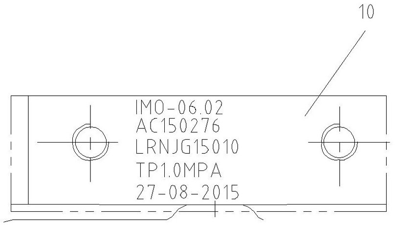
technical field [0001] The invention relates to a special tool for knocking a stamp mark on a mechanical part, in particular to a special tool and a method for knocking a product mark on the side of a cylinder head, and belongs to the technical field of mechanical processing. Background technique [0002] The cylinder head is the main key part of the diesel engine, and the stamp mark needs to be struck on the cylinder head, such as figure 1 As shown, the steel stamp mark on the cylinder head 10 of the L23 marine diesel engine has five rows of 45 characters, which are: emission number, cylinder head body number, ship inspection certificate number, water test certification number and ship inspection date. Each row of steel stamp marks is composed of letters and numbers arranged according to the writing rules. The length of the steel stamp mark area that can be tapped is about 60mm, and the width is about 35mm. The font height of the steel stamp mark is 6mm, and the tapping ran...

Claims


Application Information

Patent Timeline
Patent Type & Authority Patents(China)
IPC IPC(8): B41K3/36B41K3/62B41K3/04
Inventor 焦非黄汉龙
Owner CSSC MARINE POWER
Learn More