
Method applied to condenser inlet and outlet water chamber assembling and welding

A technology of import and export and condenser, applied in welding equipment, metal processing equipment, manufacturing tools, etc., can solve the problems that manpower is difficult to meet machining requirements, and there is no setting tool.

Inactive Publication Date: 2019-06-07
HARBIN TURBINE
View PDF8 Cites 0 Cited by
  • Summary
  • Abstract
  • Description
  • Claims
  • Application Information

AI Technical Summary

Problems solved by technology

[0003] The present invention aims to solve the technical problem that there is no shaping tool in the assembly and welding process of the inlet and outlet water chambers of the condenser, and it is difficult for manpower to meet the subsequent machining requirements, and provides a method for assembling and welding the inlet and outlet water chambers of the condenser

Method used


Image

  • Method applied to condenser inlet and outlet water chamber assembling and welding
  • Method applied to condenser inlet and outlet water chamber assembling and welding
  • Method applied to condenser inlet and outlet water chamber assembling and welding

Examples


specific Embodiment approach 1

[0017] Specific implementation mode 1: This implementation mode is a method for welding the inlet and outlet water chambers of the condenser, which is carried out according to the following steps:

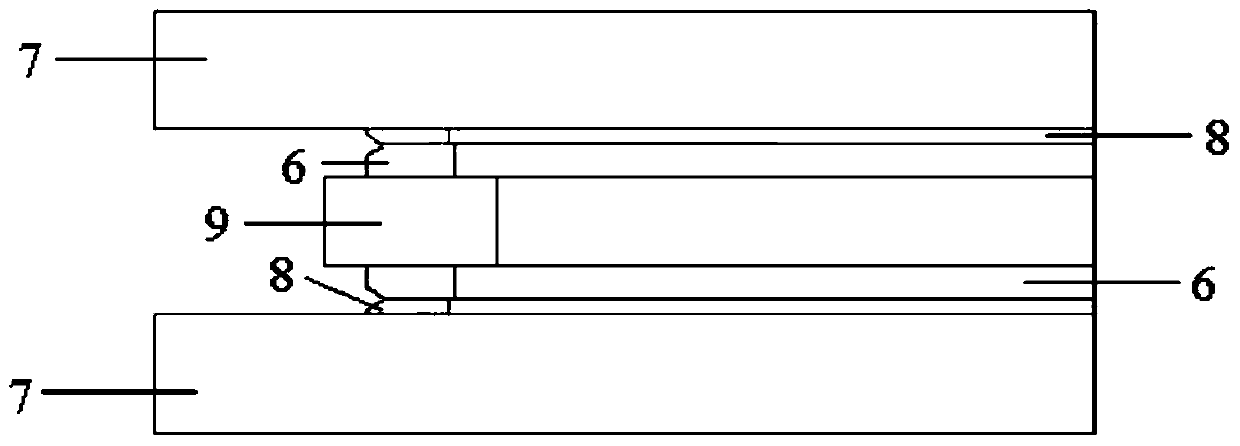
[0018] 1. Thermal leveling: if figure 1 As shown, thermal leveling: First, spot weld one end face of the two carbon steel flanges 6 on the two end faces of the welding base plate 9, and then assemble and weld the other end faces of the two carbon steel flanges 6 respectively. The cupronickel lining plate 8 is compacted with the upper and lower pressure plates 7, and then the entire workpiece is placed in the annealing furnace, and the welding stress between the carbon steel flange 6 and the cupronickel lining plate 8 is eliminated through heat treatment, the hardness is reduced and Make it level and complete the leveling work. The middle part is taken out from the two pressure plates, and the welding base plate 9 is removed to obtain the head flange and the connecting flange respe...

specific Embodiment approach 2

[0022] Embodiment 2: This embodiment differs from Embodiment 1 in that: in step 1, the other end faces of the two carbon steel flanges 6 are assembled and welded respectively, and a cupronickel liner 8 is welded together by argon arc welding. Others are the same as the first embodiment.

specific Embodiment approach 3

[0023] Embodiment 3: The difference between this embodiment and Embodiment 1 or 2 is that the heat treatment process in Step 1 is as follows: the temperature of entering and exiting the furnace is 140°C-150°C, the heating and cooling rate is 95°C-100°C, and the heat treatment temperature 570 ℃ ~ 590 ℃, keep warm for 2 hours. Others are the same as those in Embodiment 1 or 2.


PUM


Abstract

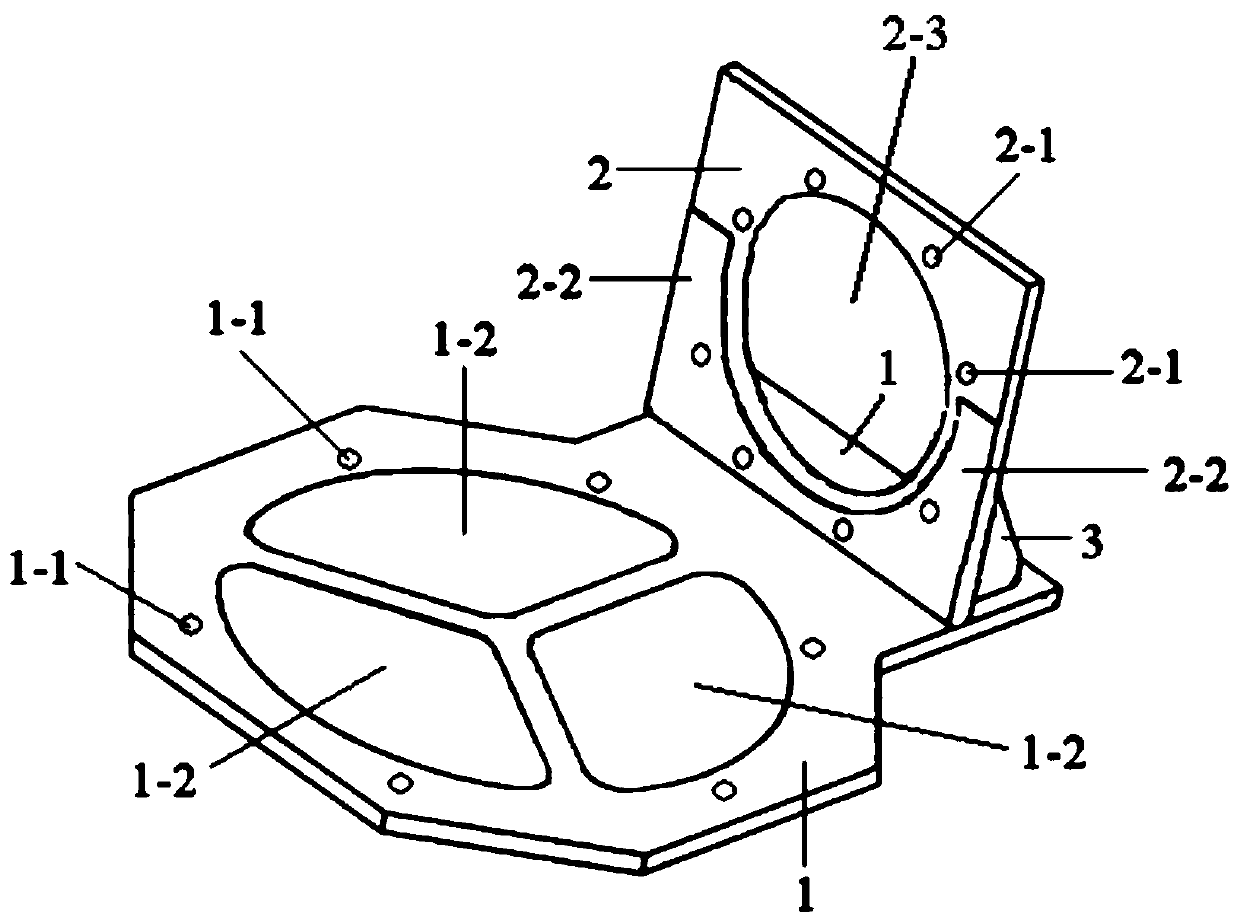
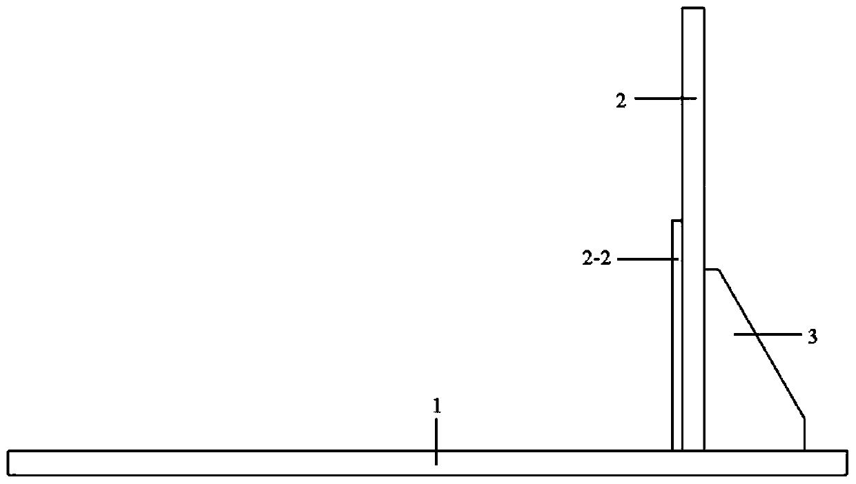
The invention discloses a method applied to condenser inlet and outlet water chamber assembling and welding, relates to a water chamber assembling and welding method, and aims at solving the technicalproblems that in the existing condenser inlet and outlet water chamber assembling and welding process, no sizing tool is adopted, and manpower difficultly meets the later machining requirement. The method comprises the steps that firstly, heat leveling is conducted; and secondly, a water chamber is placed on a tool and subjected to heat treatment together with the tool, and accordingly the methodapplied to condenser inlet and outlet water chamber assembling and welding is finished. According to the method, the condenser inlet and outlet water chamber assembling and welding deformation is controlled, the relative position of a water chamber flange and a pipe connecting flange meets the later machining requirement, and the design size requirement is met. The tool adopted in the second stepis simple in structure and convenient and fast to use, and the machining requirement after inlet and outlet water chamber flange assembling and welding is met.

Description

technical field [0001] The invention relates to a method for installing and welding a water chamber. Background technique [0002] During the assembly and welding process of the inlet and outlet water chambers of the condenser, since there are no shaping tools, it is almost impossible to ensure that the axes of the water chamber flange and the connecting pipe flange are vertical to meet the subsequent machining requirements only by the structure of the parts themselves and the artificial control of the welding process. , After the assembly and welding, it is always necessary to repair the welding flange to meet the subsequent machining requirements, which wastes manpower and material resources and cannot guarantee product quality. Contents of the invention [0003] The present invention aims to solve the technical problem that there is no shaping tool in the assembly and welding process of the inlet and outlet water chambers of the condenser, and it is difficult for manpow...

Claims


Application Information

Patent Timeline
Patent Type & Authority Applications(China)
IPC IPC(8): B23P15/00B23K31/02
Inventor 高作为李宝磊徐翔任国锋张辰鸾王莉莉张宇航谭延宏曲文龙苏志成
Owner HARBIN TURBINE
Learn More