
Electric hair cutter and control method thereof

A control method and the technology of electric clippers, which are applied in metal processing and other directions, can solve the problem of inconvenient adjustment of the length of the matching comb, and achieve the effects of saving shell space, convenient holding, and precise length change

Inactive Publication Date: 2019-06-07
ZHEJIANG YUELI ELECTRICAL
View PDF11 Cites 2 Cited by
  • Summary
  • Abstract
  • Description
  • Claims
  • Application Information

AI Technical Summary

Problems solved by technology

[0008] The present invention intends to provide an electric clipper to solve the problem that the existing electric clippers are inconvenient to adjust the comb length

Method used


Image

  • Electric hair cutter and control method thereof
  • Electric hair cutter and control method thereof

Examples


Embodiment 1

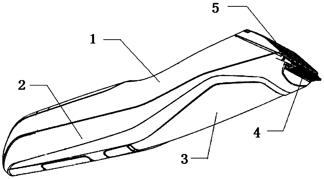
[0054] The first embodiment is basically as attached figure 1 Shown: electric clippers, including a shell and a blade assembly 4 and a comb 5 installed at the front end of the shell. The front end of the housing refers to the end of the electric clipper close to the hair during operation. The shell includes an upper shell 1 and a lower shell 2 buckled with each other. The lower shell 2 is equipped with a touch panel 3 for adjusting the extension length of the comb 5. When the touch panel 3 has multiple gears, the length of the comb 5 protruding from the shell is different when different gears are touched.

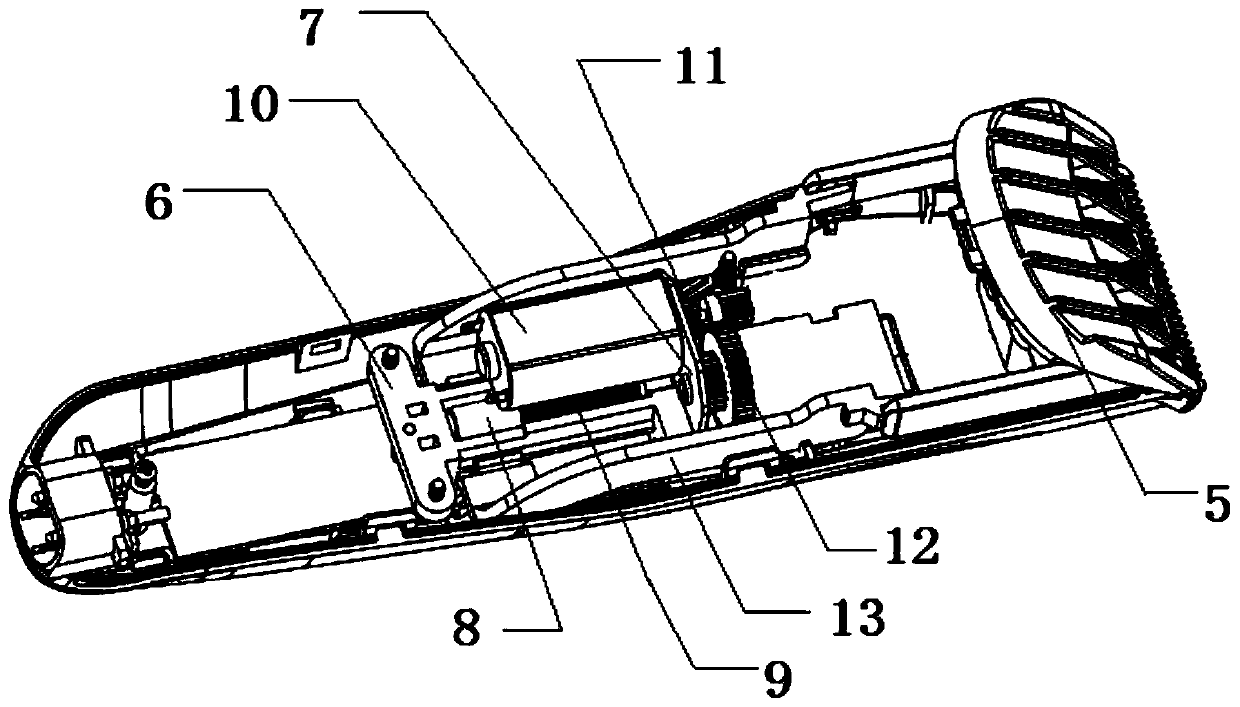
[0055] The blade assembly 4 is driven by an electric mechanism installed in the housing for reciprocating motion. For its structure, please refer to the blade set and drive mechanism in the patent document of the publication number CN201633051U or other connection structures of existing electric clippers. This is the prior art. I will not repeat them here.

[0056] Such as fi...

Embodiment 2

[0068] The difference between this embodiment and the first embodiment is that the driving part in this embodiment is a nut, and the driven part is a screw. The rear end of the screw is connected to the movable seat through a bearing, so that the screw can rotate relative to the movable seat and at the same time can drive the movable seat to move back and forth.

Embodiment 3

[0070] The difference between this embodiment and the first embodiment is that the detector in this embodiment adopts a photoelectric encoder, and the photoelectric encoder is electrically connected to the base of each triode.


PUM


Abstract

The invention relates to the technical field of trimming tools, and specifically discloses an electric hair cutter. The electric hair cutter comprises a housing and a matched comb which is arranged atthe front end of the housing, wherein a touch panel is arranged on the housing; controllable silicon which is electrically connected to the touch panel as well as a motor and a detector which are separately connected to the controllable silicon electrically are arranged in the housing; the motor and the touch panel are in series connected to the controllable silicon; the motor is used for drivingthe matched comb to move; and the detector is used for blocking the controllable silicon after number of rotation rings of the detector is detected to reach a set value. The invention further discloses a control method of the electric hair cutter. The electric hair cutter effectively solves the problem that an existing electric hair cutter is inconvenient in regulating length of the matched comb.

Description

Technical field [0001] The invention relates to the technical field of trimming tools, in particular to an electric clipper for trimming hair and its control method. Background technique [0002] Electric hair clippers generally include a housing and a blade assembly arranged at the front end of the housing for hair trimming; the housing is provided with an electric mechanism for driving the blade to reciprocate. In order to facilitate people to control the hair trimming length, a comb is generally installed between the housing and the blade assembly to reduce the contact length between the blade assembly and the hair. Matching comb, also known as limit comb, is a comb-like structure without cutting edges. [0003] When using electric hair clippers, you must first select a comb with a suitable length, and then manually install the selected comb on the housing to form a gap between the blade assembly and the comb, and avoid direct contact between the blade assembly and the skin. W...

Claims


Application Information

Patent Timeline
Patent Type & Authority Applications(China)
IPC IPC(8): B26B19/20B26B19/38
Inventor 方国洪
Owner ZHEJIANG YUELI ELECTRICAL
Learn More