
Compact coil optical waveguide supporting on-chip long-distance low-loss transmission

A long-distance, low-loss technology, applied in the field of integrated optics, can solve the problems of low transmission loss optical waveguide delay line, increased mode mismatch loss, large device size, etc., to achieve compact structure, precise length change, and low loss. Effect

Active Publication Date: 2022-04-01
ZHEJIANG UNIV
View PDF12 Cites 0 Cited by
  • Summary
  • Abstract
  • Description
  • Claims
  • Application Information

AI Technical Summary

Problems solved by technology

Although the design of this scheme is simple, the overall size of the device is too large, and the mode mismatch loss at the junction of the curved waveguide and the straight waveguide will increase exponentially with the increase of the propagation distance, which makes it difficult to achieve performance in the current standard process. Optical waveguide delay line that supports on-chip long-distance transmission with compact structure and low transmission loss

Method used


Image

  • Compact coil optical waveguide supporting on-chip long-distance low-loss transmission
  • Compact coil optical waveguide supporting on-chip long-distance low-loss transmission
  • Compact coil optical waveguide supporting on-chip long-distance low-loss transmission

Examples


Embodiment Construction

[0035] The present invention will be further described below in conjunction with the accompanying drawings and embodiments, but the protection scope of the present invention should not be limited thereby.

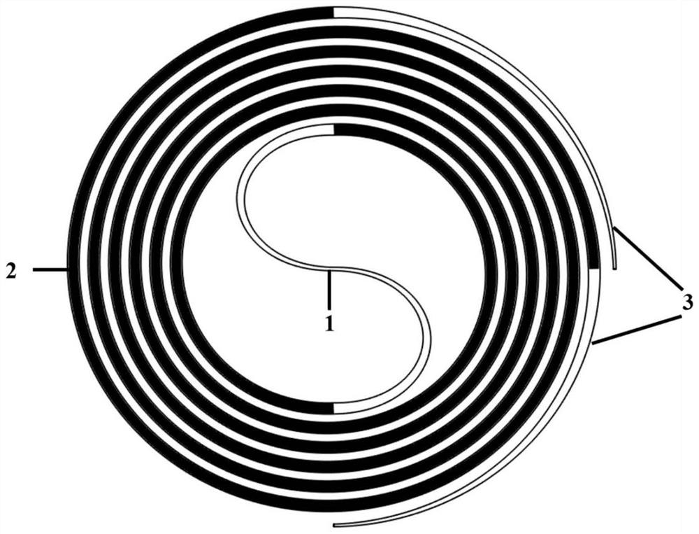
[0036] Such as figure 1 As shown, the specific implemented device structure includes an S-shaped curved waveguide 1 with a gradually changing width and radius, two curved coil waveguides 2 with a gradually changing radius, and two curved curved waveguides 3 with a gradually changing width and radius; the S-shaped curved waveguide 1 with a gradually changing width and radius The center of the curved waveguide 2 with tapered radius coils, the two ends of the curved waveguide 1 with tapered radius gradients are respectively connected to the inner ends of two curved waveguides 2 with tapered radius coils, and the outer ends of the two curved waveguides 2 with tapered radius coils are alternately helically arranged Two arc-shaped curved waveguides 3 with gradually changing width...


PUM


Abstract

The invention discloses a compact coil optical waveguide supporting on-chip long-distance low-loss transmission. The waveguide comprises an S-shaped bent waveguide with a gradually-changed width radius, two coil bent waveguides with gradually-changed radiuses and two arc-shaped bent waveguides with gradually-changed width radiuses, the S-shaped bent waveguide with the gradually-changing width radius is arranged at the center of the two coil bent waveguides with the gradually-changing radius, and the two ends of the S-shaped bent waveguide with the gradually-changing width radius are connected with the inner ends of the two coil bent waveguides with the gradually-changing radius respectively. The outer ends of the two radius-gradually-changing coil bending waveguides which are alternately and spirally arranged are respectively connected with the two width radius-gradually-changing arc-shaped bending waveguides. According to the optical waveguide, on the premise that input light is kept to be transmitted in a fundamental mode, long-distance transmission can be conducted on a chip with low loss, the size of the optical waveguide is reduced while scattering loss and inter-mode crosstalk are reduced, and the optical waveguide can be used for systems such as an adjustable optical delay line and an optical coherence tomography scanner.

Description

technical field [0001] The invention belongs to an optical waveguide delay line in the field of integrated optics, and in particular relates to a compact coil optical waveguide supporting on-chip long-distance low-loss transmission. Background technique [0002] With the development of photonic integration technology, many optical devices have achieved large-scale integration on chip and are gradually applied in high-speed communication, signal processing and sensing. The goal of integrated optics is to integrate all optical devices such as lasers, modulators, waveguides, detectors, etc. on a chip with high density and can be produced on a large scale, which requires the fabrication platform to require high refractive index of its waveguide layer and outer cladding Poor and compatible with the current CMOS process and other characteristics, this makes silicon-on-insulator (SOI) stand out among many platforms and has developed rapidly in recent years. At the same time, the h...

Claims


Application Information

Patent Timeline
Patent Type & Authority Applications(China)
IPC IPC(8): G02B6/28G02B6/122
Inventor 戴道锌洪仕瀚
Owner ZHEJIANG UNIV
Learn More