
Data slicer, data slicing method, and amplitude evaluation value setting method

a data slicer and amplitude evaluation technology, applied in the field of data slicer, data slicing method, and amplitude evaluation value setting method, can solve the problems of circuit scale so large, reduced electric field strength, and increased probability of occurrence of decoding errors, so as to achieve the effect of reducing the number of errors

Inactive Publication Date: 2006-08-29
SOCIONEXT INC
View PDF14 Cites 18 Cited by
  • Summary
  • Abstract
  • Description
  • Claims
  • Application Information

AI Technical Summary

Benefits of technology

The present invention provides a data slicer, method, and apparatus for extracting data from a digital video signal. The invention can suppress errors in decoding caused by distortion in the video signal due to group delay or reduction in electric field strength. The invention includes an A / D conversion unit, slice level data calculation unit, binarization unit, extraction pulse generation unit, decoding unit, decoded data selection unit, and a reference cycle detection unit. The invention also provides a method for detecting the reference waveform in a video signal and obtaining slice level data accordingly. The technical effects of the invention include reducing the occurrence rate of decoding errors and improving the accuracy of data extraction.

Problems solved by technology

However, the analog video signal S110 that is inputted from the video signal input terminal 110 may include distortion resulting from group delay or reduction in electric field strength in a transmission system.
Further, as the slice level calculation is performed only in the CRI detection period, improper slice level data are obtained when the shape of the digital video signal S140 varies after the CRI signal C. Consequently, the binarization circuit 221 binarizes the signal into an improper value, whereby the probability of occurrence of decoding errors is increased.
Further, when a waveform equalization filter is used to correct distortion of the waveform in the transmission system, the circuit scale is so large that the circuit scale of the data slicer is adversely increased.

Method used


Image

  • Data slicer, data slicing method, and amplitude evaluation value setting method
  • Data slicer, data slicing method, and amplitude evaluation value setting method
  • Data slicer, data slicing method, and amplitude evaluation value setting method

Examples


embodiment 1

[0075]A data slicer according to a first embodiment of the present invention will be described with reference to the drawings.

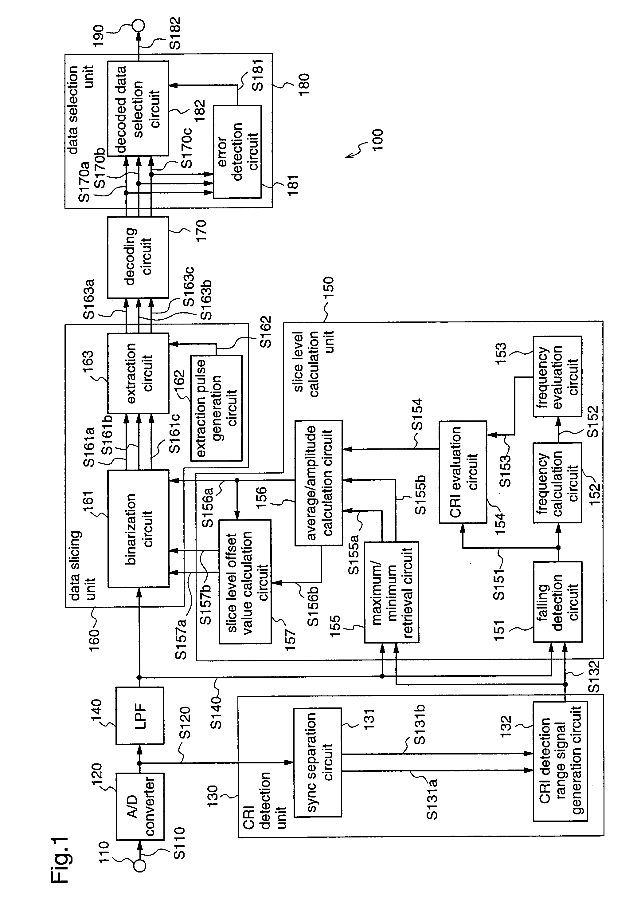
[0076]FIG. 1 is a block diagram illustrating a construction of the data slicer according to the first embodiment.

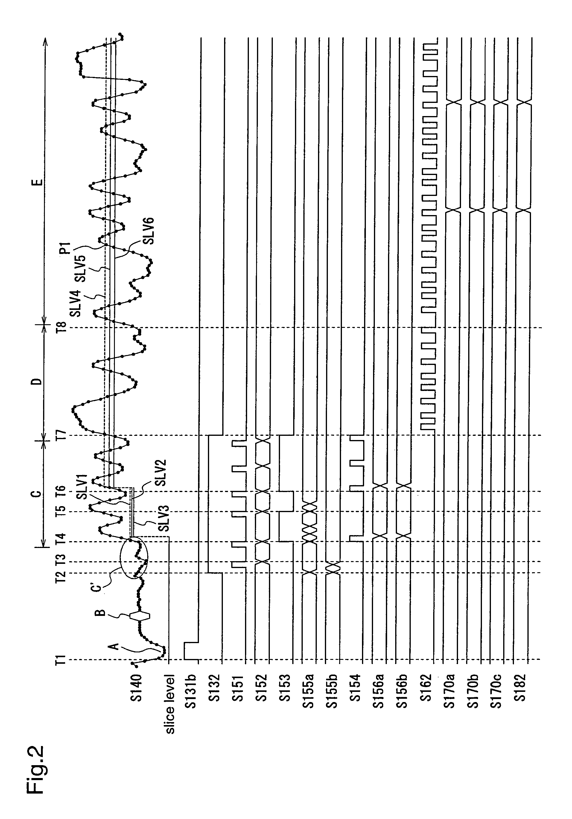
[0077]As shown in FIG. 1, the data slicer 100 according to the first embodiment includes an A / D converter 120 that converts an analog video signal S110 inputted through a video signal input terminal 110, upon which character broadcast serial data are superimposed, into a digital video signal S120; a CRI detection unit 130 that outputs a CRI detection range signal S132 indicating a clock run-in (hereinafter, referred to as CRI) detection period, on the basis of the digital video signal S120; a low-pass filter (hereinafter, referred to as LPF) 140 that eliminates noises from the digital video signal S120, and outputs a digital video signal S140; a slice level calculation unit 150 that calculates a slice level and a slice level offset on the basis of ...

embodiment 2

[0101]A data slicer according to a second embodiment of the present invention will be described with reference to the drawings.

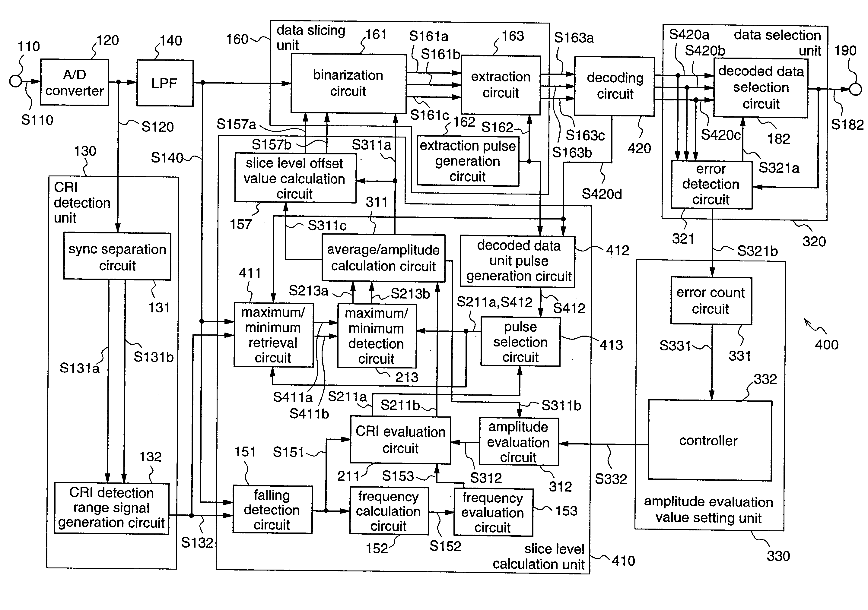
[0102]FIG. 3 is a block diagram illustrating a construction of a data slicer 200 according to the second embodiment. In FIG. 3, the same or corresponding elements as shown in FIG. 1 are denoted by the same reference numerals.

[0103]As shown in FIG. 3, the data slicer 200 according to the second embodiment includes an A / D converter 120 that converts an analog video signal S110 inputted through a video signal input terminal 110, upon which character broadcast serial data are superimposed, into a digital video signal S120; a CRI detection unit 130 that generates a CRI detection range signal S132 indicating a CRI detection period on the basis of the digital video signal S120; a LPF 140 that eliminates noises of a predetermined band from the digital video signal S120, and outputs a digital video signal S140; a slice level calculation unit 210 that determines wheth...

embodiment 3

[0132]A data slicer and an amplitude evaluation value setting method according to a third embodiment of the present invention will be described with reference to the drawings.

[0133]FIG. 5 is a block diagram illustrating a construction of a data slicer 300 according to the third embodiment. In FIG. 5, the same or corresponding elements as those in FIG. 3 are denoted by the same reference numerals.

[0134]As shown in FIG. 5, the data slicer 300 according to the third embodiment includes an A / D converter 120 that converts an analog video signal S110 inputted through a video signal input terminal 110, upon which character broadcast serial data are superimposed, into a digital video signal S120; a CRI detection unit 130 that generates a CRI detection range signal S132 indicating a CRI detection period, on the basis of the digital video signal S120; a LPF 140 that eliminates noises from the digital video signal S120, and outputs a digital video signal S140; a slice level calculation unit 31...


PUM


Abstract

A data slicer 300 includes a slice level calculation unit 310 that determines whether a detected digital video signal is a CRI signal on the basis of the amplitude of the signal, and sets a reference slice level and upper and lower slice levels which are obtained by providing offset in the reference slice level, by using only the CRI signal; a data slicing unit 160 that binarizes a digital video signal S140 using the slice levels; a decoding circuit 170 that converts binarized serial data into parallel data; and a data selection unit 320 that selects data including no error from the decoded data, and outputs the selected data through a video signal output terminal 190. Therefore, even when the video signal is distorted, this data slicer can set appropriate slice level data to binarize the video signal, thereby suppressing the occurrence rate of decoding errors.

Description

FIELD OF THE INVENTION[0001]The present invention relates to a data slicer, a data slicing method, and an amplitude evaluation value setting method and, more particularly, to a data slicer, a data slicing method, and an amplitude evaluation value setting method for calculating a slice level that enables to binarize a video signal into a proper value.BACKGROUND OF THE INVENTION[0002]As a method for transmitting data utilizing serial transmission, there is a character broadcast system by which character broadcast data are transmitted in vertical blanking intervals of video signals.[0003]There are various kinds of character broadcast systems that employ different superimposition lines upon which character broadcast data (character broadcast serial data) are superimposed, or transmission clocks of different frequencies, and various kinds of analog video signals on which the character broadcast serial data are superimposed are transmitted at present in various regions over the world.[000...

Claims


Application Information

Patent Timeline
Patent Type & Authority Patents(United States)
IPC IPC(8): H04N7/00H04N7/025H04N7/03H04N7/035H04N7/083H04N7/087H04N7/088
CPCH04N7/035H04N7/0882H04N7/0357H04N7/0355
Inventor SUZUKI, AKIHIROKUZUMOTO, KEIICHI
Owner SOCIONEXT INC
Learn More