Electrostatic liquid spray nozzle having an internal dielectric shroud

a technology of dielectric shroud and nozzle, which is applied in the direction of electrostatic spraying apparatus, burners, lighting and heating apparatus, etc., to achieve the effect of reducing the intensity of the electric field and preventing leakage curren

Active Publication Date: 2014-04-24
E S PROD DEV
View PDF5 Cites 18 Cited by
  • Summary
  • Abstract
  • Description
  • Claims
  • Application Information

AI Technical Summary

Benefits of technology

[0010]The nozzle has a nozzle body including an inlet for receiving a liquid and a liquid tip having an outlet at a distal end for ejection of the liquid. An electrode is disposed around the outlet of the liquid tip for generating an electric field between the electrode and the liquid for charging the liquid. A dielectric shroud is disposed around at least a portion of the liquid tip to prevent leakage currents from reducing an intensity of the electric field. The dielectric shroud may be in the form of an annulus disposed around the base of the liquid tip. A conductor that supplies the electrode may extend through a passage in the dielectric shroud in a direction parallel to the central axis of the annulus. The dielectric shroud may define one or more apertures passing through the shroud for permitting liquid and / or gas to pass through.

Problems solved by technology

However, use of induction charging methods in the room, equipment and furniture sanitizing applications above typically requires field serviceability and robustness of the design to both servicing as well as providing continuous and extended use of the system.

Method used


Image

  • Electrostatic liquid spray nozzle having an internal dielectric shroud
  • Electrostatic liquid spray nozzle having an internal dielectric shroud
  • Electrostatic liquid spray nozzle having an internal dielectric shroud

Examples


Embodiment Construction

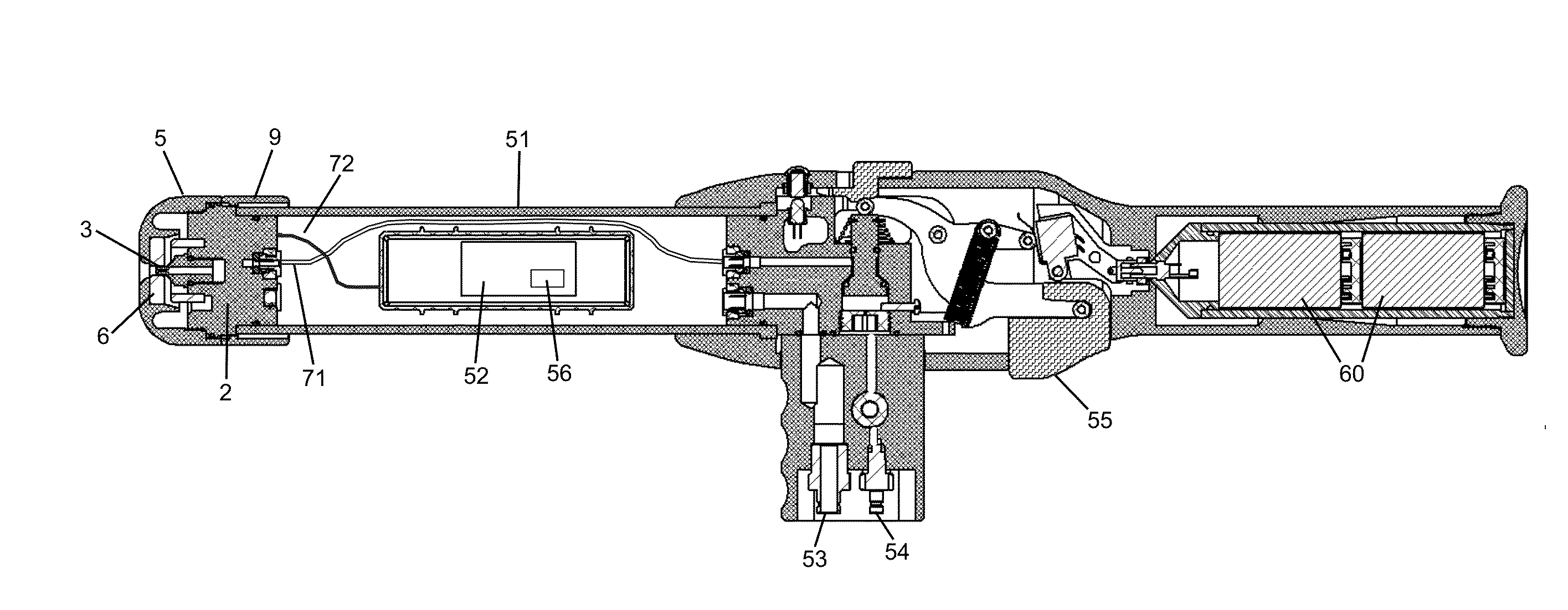
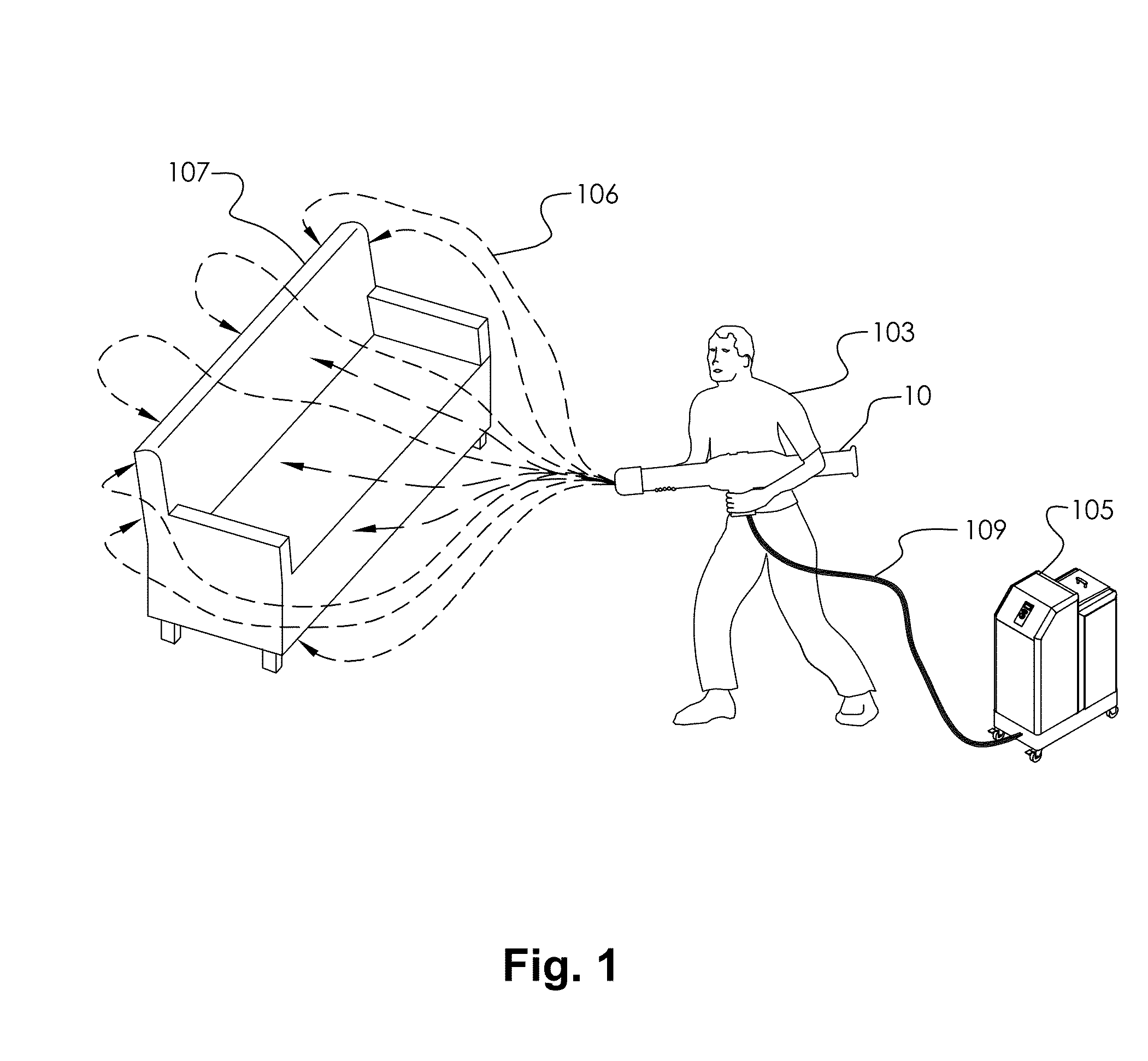
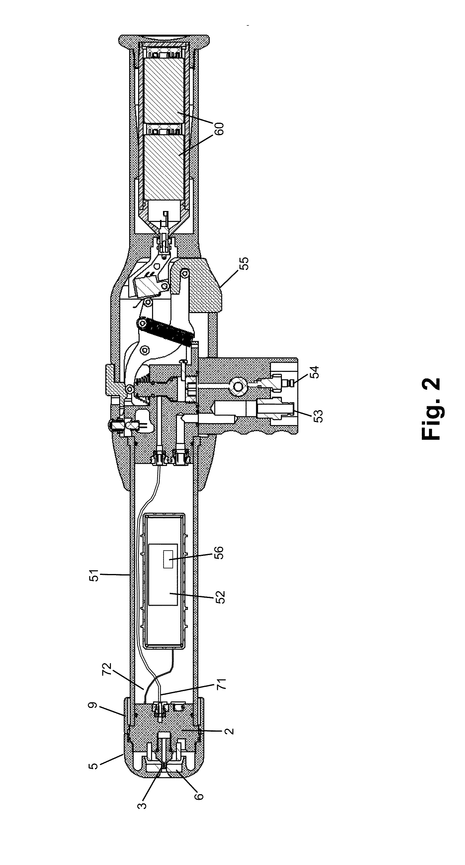
[0020]The present invention concerns electrostatic spray nozzle features, specifically features of and around a liquid tip that reduce liquid accumulation and reduction of an electrostatic charging field surrounding a liquid stream ejected by the liquid tip. Non-contact induction liquid spray charging systems operate by surrounding the spray stream at the atomization zone with an electrode, creating a non-contacting charging field between the electrode and the liquid. Pneumatic energy is often used in induction-charging nozzle systems for atomization and air assisted delivery of spray. High velocity gas, usually compressed air, passes through the gap between electrode and liquid tip. The air generally keeps the liquid from contacting the electrode, which could reduce the charging field or, in the worst case, create a direct electrical short circuit. Distinct advantages of properly implemented induction-charging systems are: the liquid reservoir can be held at or near earth potential...


PUM


Abstract

An electrostatic sprayer for spraying a liquid includes a nozzle formed from a a nozzle body that has an inlet for receiving a liquid and a liquid tip having an outlet for ejection of the liquid to form a liquid spray. The nozzle also includes an electrode disposed around the outlet of the liquid tip for charging the liquid and a dielectric shroud disposed around at least a portion of the liquid tip to prevent leakage currents from reducing a potential of the electric field between the liquid and the electrode, which would otherwise reduce the effectiveness of the sprayer. A conductor that couples the electrode to a power supply may pass through a hole extending through the shroud. The shroud may include one or more vents to permit air and liquid to pass through the dielectric shroud to reduce accumulation of liquid.

Description

[0001]This U.S. Patent Application claims priority under 35 U.S.C. 119(e) to U.S. Provisional Patent Application Ser. No. 61 / 716,884 filed on Oct. 22, 2012.BACKGROUND OF THE INVENTION[0002]1. Field of the Invention[0003]The present invention relates to electrostatic liquid spray systems, and in particular a nozzle for an electrostatic liquid spray system having an internal dielectric shroud.[0004]2. Background of the Invention[0005]An electrostatic spraying process charges either powder or liquid particulate to improve spray delivery and deposition. Advantages of the electrostatic charging are uniform spray cloud dispersion as well as improved uniformity and mass transfer efficiency in coating of target surfaces. In practice, many types of target surfaces are coated by electrostatic sprays; varying from agricultural crops to automobiles, appliances, furniture and many other manufactured goods. Unique opportunities for electrostatic spraying are still emerging. For example, recently ...

Claims


Application Information

Patent Timeline
Patent Type & Authority Applications(United States)
IPC IPC(8): B05B5/043
CPCB05B5/043B05B5/03B05B7/066B05B5/087B05B7/0441B05B7/22
Inventor COOPER, STEVEN C.
Owner E S PROD DEV
Why Eureka
Try Eureka